-
- Week8 Overview
- My Personal assignment
- Summarize the core knowledge points of Electronics Design.
- Tools、Software & Machine Introduction
- Design Schematic of Dao Clock
- Design PCB files of Dao Clock
- From Gerber to G-Code
- Machining the PCB and checking the Circuit
- Make the BOM for Dao Clock PCB
- Solder components onto the PCB
- Some Problems and Solutions
- Test the PCB
- The Hero Shots
- Team assignment
- Assignment files
week08-Electronics Design
Week 8 - Overview
Components
- Basic Components: Learning about resistors, capacitors (both polarized and unpolarized), diodes (including PN, Schottky, Zener, and LEDs), and transistors (bipolar and MOSFET).
- Complex Components: Understanding the functions and applications of crystals, resonators, inductors, batteries, regulators, DC-DC converters, op-amps, microcontrollers, sensors, and actuators.
- Connectors and Wiring: Introduction to using ribbon cables and IDC connectors.
Circuit Design
- Fundamentals: Covered the basics of current, voltage, and power, including Kirchoff’s laws.
- Electronic Design Automation (EDA): Explored tools and processes such as sketching, schematic entry, component placement, routing, simulation, and fabrication.
- Software Tools: Learned to use various EDA software like Tinkercad, Fritzing, KiCad, Eagle, and Altium for designing and simulating circuits.
Testing and Simulation
- Test Equipment: Usage of tools like power supplies, multimeters, oscilloscopes, and logic analyzers for testing and debugging circuits.
- Simulation Software: Gained experience with simulation tools including SPICE, LTspice, and Multisim to model both analog and digital circuits.
- use the test equipment in your lab to observe the operation of a microcontroller circuit board
- send a PCB out to a board house
- use an EDA tool to design a development board to interact and communicate with an embedded microcontroller,produce it, and test it
- extra credit: try another design workflow
- extra credit: design a case for it
- extra credit: simulate its operation
Reference Links
Week8 Electronics Design Guide for my Fab Academy Journey.My personal assignment
1.Summarize the core knowledge points of Electronics Design.
Fundamental Electronic Circuit Formulas:
- Resistor: Ohm’s Law, \( I = \frac{V}{R} \), where \( I \) is current, \( V \) is voltage, and \( R \) is resistance.
- Capacitor: Capacitance formula, \( C = \frac{Q}{V} \), and the current through a capacitor, \( I = C \frac{dV}{dt} \), where \( C \) is capacitance, \( Q \) is charge, \( V \) is voltage, and \( t \) is time.
- Inductor: Inductance formula, \( V = L \frac{dI}{dt} \), where \( L \) is inductance, \( I \) is current, and \( t \) is time.
- Power Calculations: \( P = I^2R \) and \( P = IV \), where \( P \) is power, \( I \) is current, \( R \) is resistance, and \( V \) is voltage.
• Resistor: A device that impedes current flow, critical for controlling circuit conditions.
• Capacitor: An energy-storage component that comes in two types: polarized and unpolarized.
• Diode: A component that permits current flow in one direction only, with varieties such as PN, Schottky, Zener, and LED.
• Transistor: Used for switching or amplifying electronic signals, available as bipolar or MOSFET types.
• Inductor: Stores energy magnetically, often used for filtering applications.
• Microcontroller: A compact integrated circuit designed for specific tasks within an embedded system.
• Sensors and Actuators: Components that detect environmental changes and act accordingly, respectively.
• Circuit Analysis: Emphasizes Kirchoff’s laws for summing currents at a node and voltages around a loop.
• Electronic Design Automation (EDA): Covers tools for sketching, schematic entry, component placement, routing (including auto-routing), simulation, and fabrication.
• Circuit Properties: Discusses layers, angles, vias, power planes, and ground pours essential for PCB design.
• Compliance and Verification: Focuses on design rules, Design Rule Check (DRC), and Electrical Rule Check (ERC) to ensure circuit reliability and functionality.
The thickness of a PCB can vary depending on the application, from very thin (like flex PCBs) to quite thick for high-power applications.
The number of layers can range from a single layer to more than a dozen in complex electronic products.
Trace width is critical for determining the current-carrying capacity of the traces and avoiding heat buildup.
Pads and Nets are the small areas of copper where components are soldered to the board, and nets are the electrical connections between them.
Using a small CNC for PCB machining involves designing the board in CAD software, then using CAM software to generate the toolpaths.
The CNC then mills the board based on these paths.
It's a precise process that requires careful setup and calibration.
Soldering involves attaching components to the PCB by melting solder around their contacts.
Techniques vary from manual soldering for prototypes and small batches to automated processes like reflow soldering for production.
Proper soldering is crucial for reliable electrical connections.
2.Tools、Software & Machine Introduction
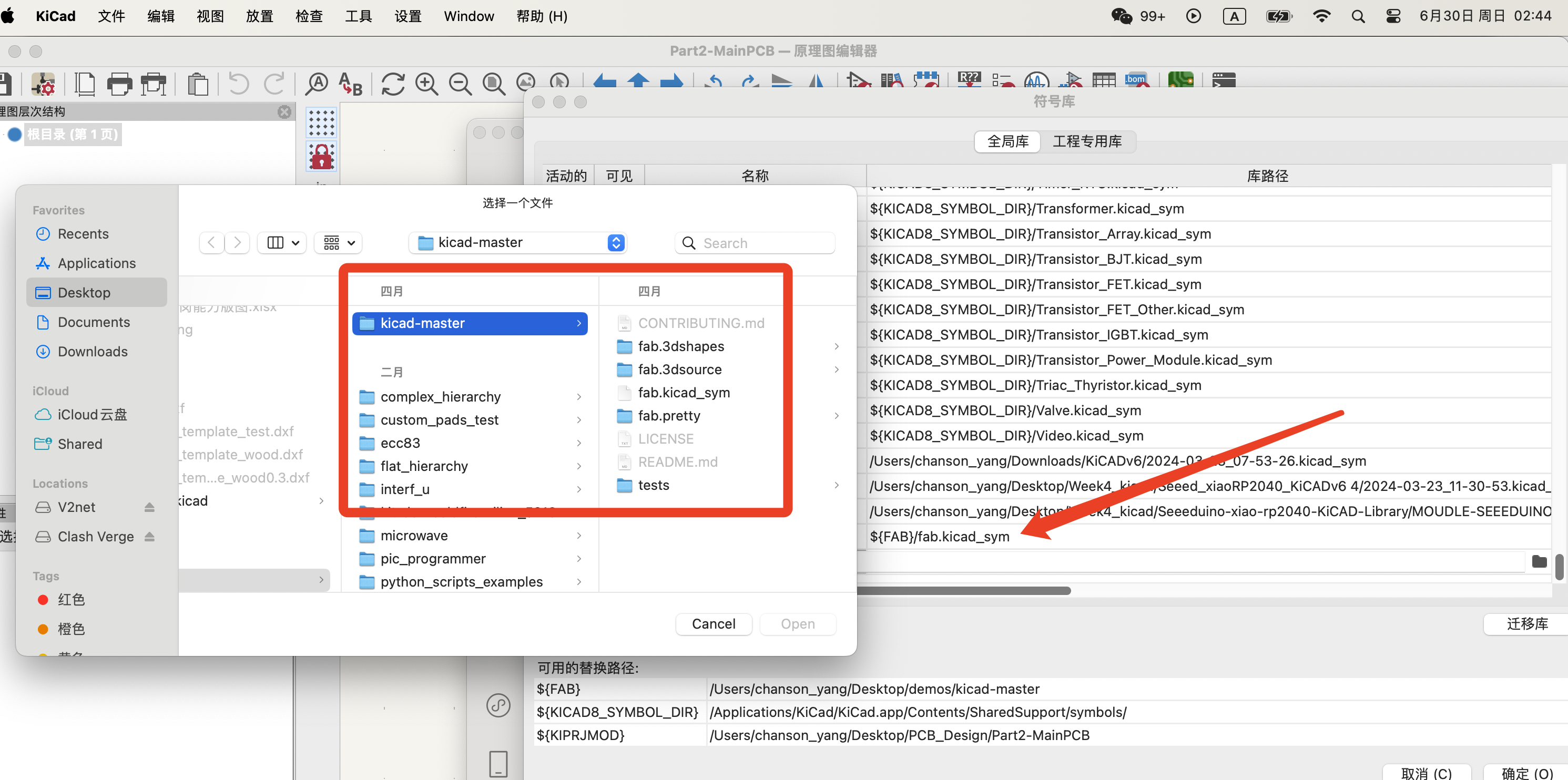
Software:Kicad
KiCad is a free and open-source electronics design automation (EDA) suite.
It features schematic capture, integrated circuit simulation, printed circuit board (PCB) layout, 3D rendering, and plotting/data export to numerous formats.
KiCad also includes a high-quality component library featuring thousands of symbols, footprints, and 3D models.
KiCad has minimal system requirements and runs on Linux, Windows, and macOS.
Learn the various functions of KiCad.


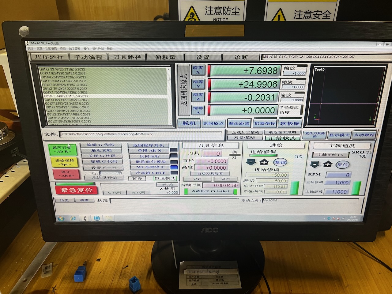
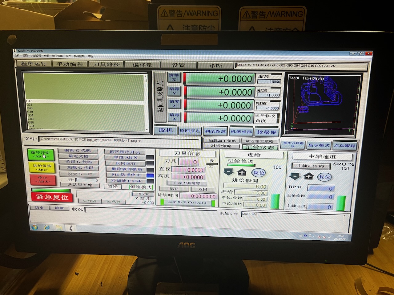
Software:Mach3 • Software to control the CNC machine, used for initializing the equipment, setting tool positions, and loading and executing G-code.
• Allows manual control of the machine’s movement and adjustment of spindle and feed rates.
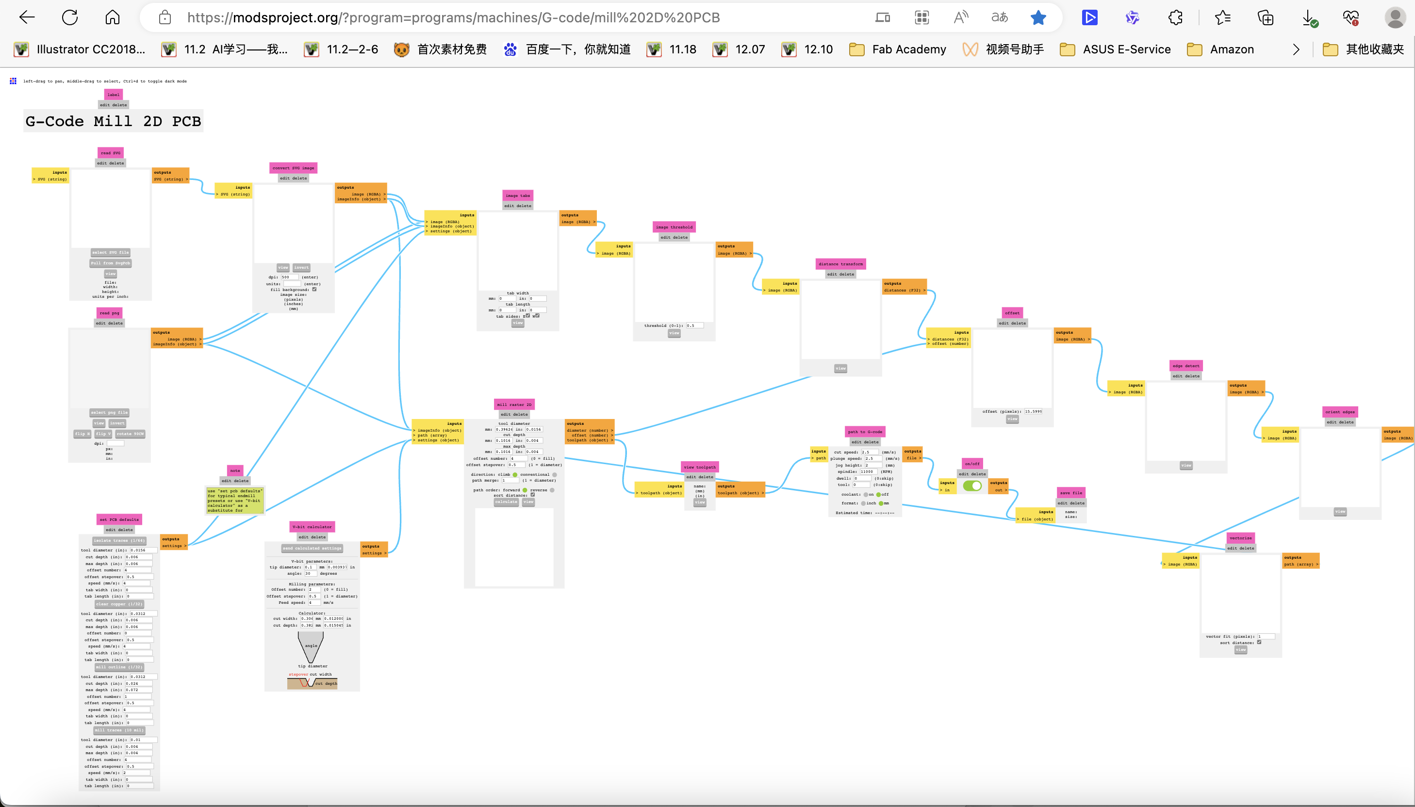
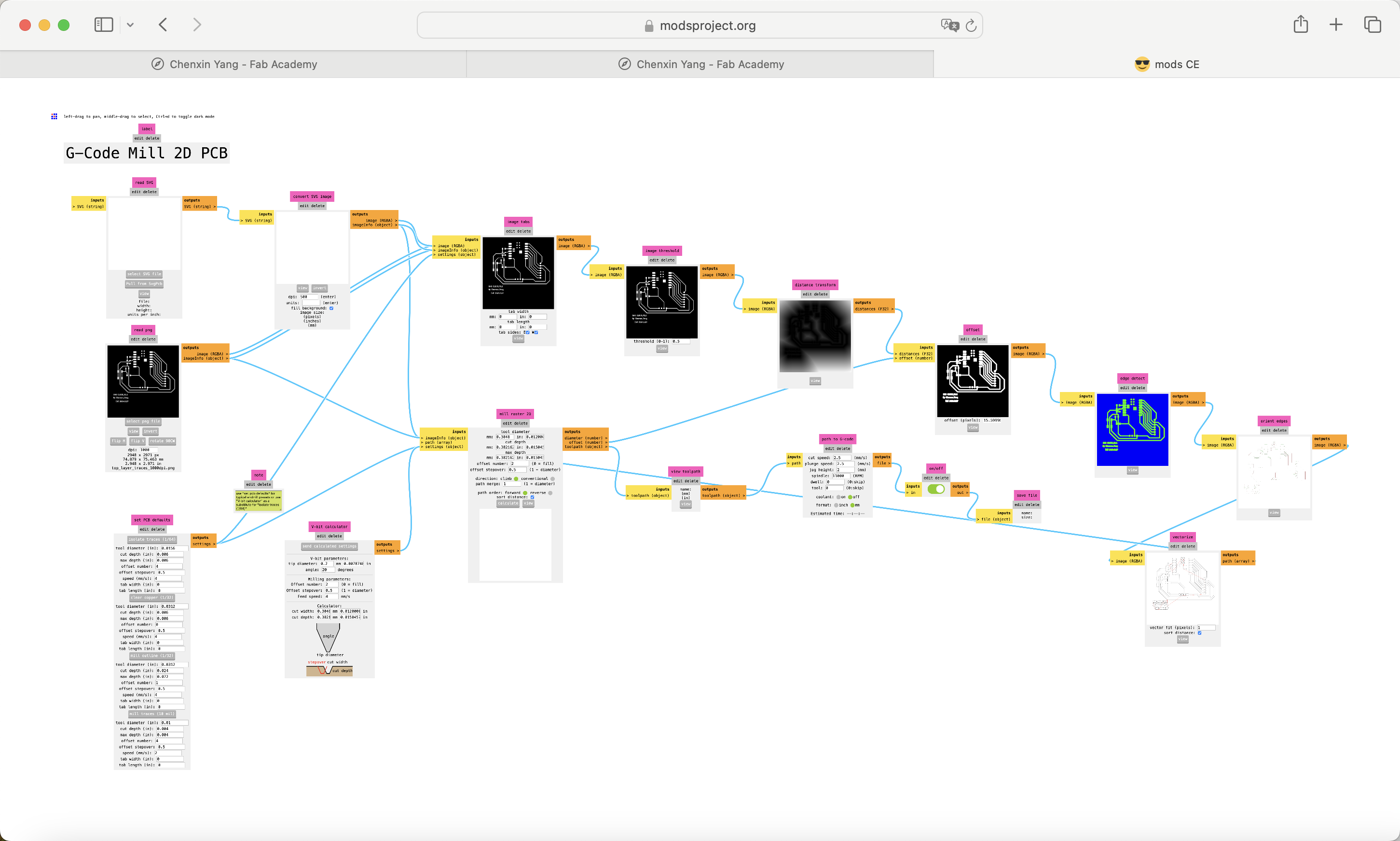
Software:G-Code Mill 2D PCB • An online tool for converting PNG images to G-code.
• Supports setting specific parameters like dots per inch (DPI) and tip diameter to accommodate different milling needs.
Software:Gerber2PNG • An online tool for converting Gerber files to PNG.
• Allows users to upload a Gerber file and convert it to a PNG image.
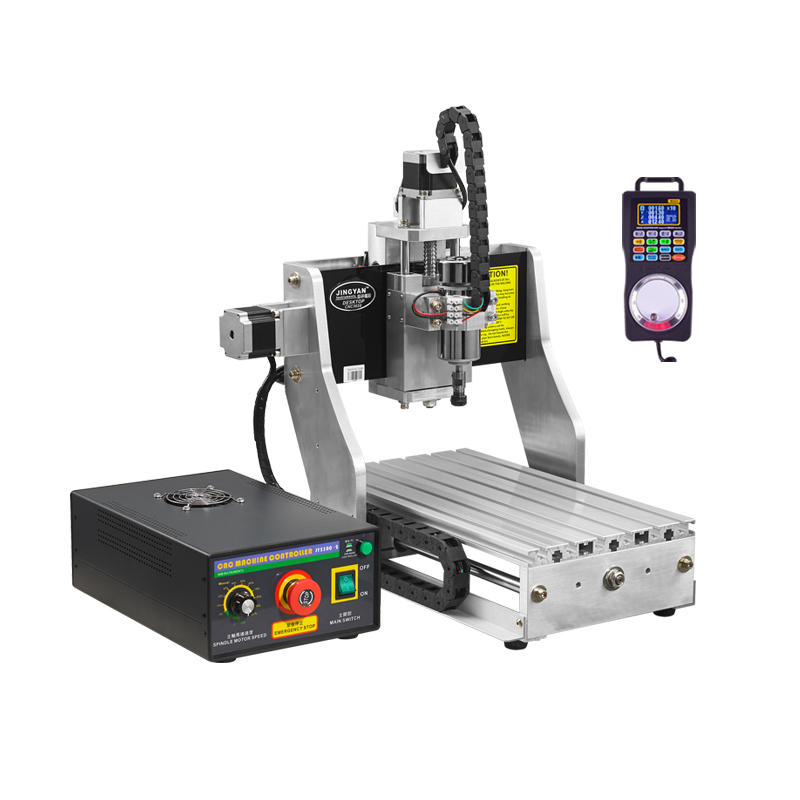
Machine:JING YAN CNC JING YAN CNC is a small CNC machine that can be used for PCB manufacturing.
The model in Chaihuo is JING YAN CNC-3020, which is a small Engraving Machine with 300w power and 300mm x 200mm working area.
Applicable Material: Copper, Aluminum and other soft metal,Plastic, Wood,Acrylic, PVC,PCB,etc....
Tools:
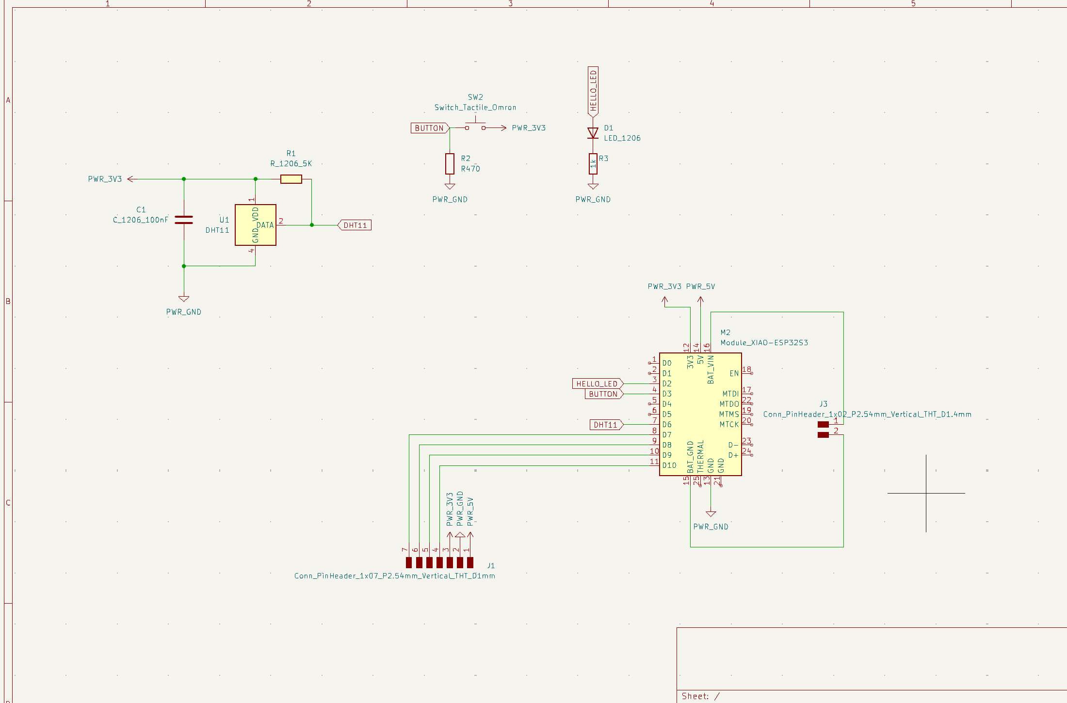
3.Design Schematic of Dao Clock
Due to the structural design of my project, I plan to place a test LED and a DHT11 on my PCB.
The rest of the components will be connected using pin interfaces.
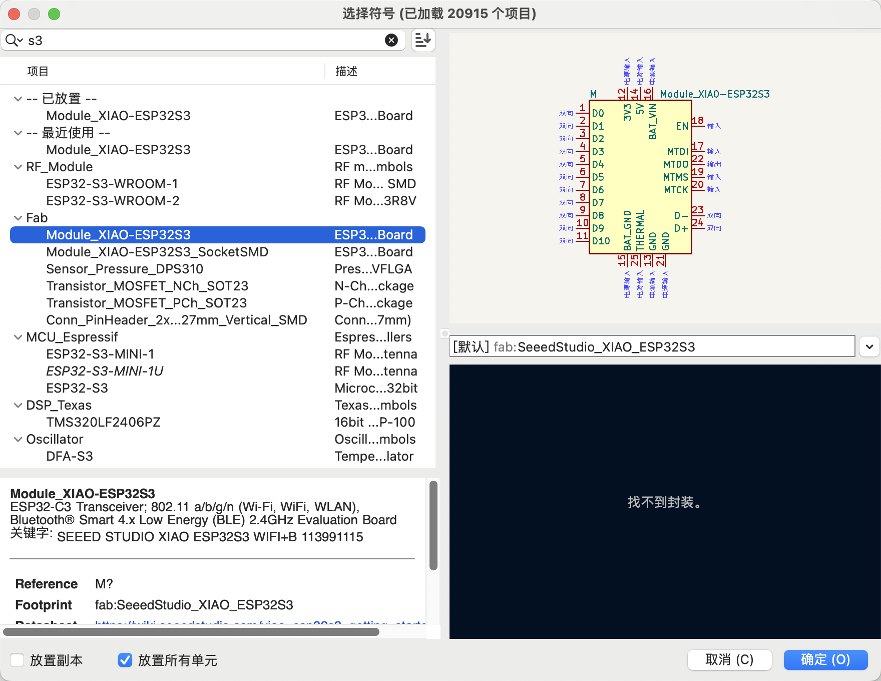
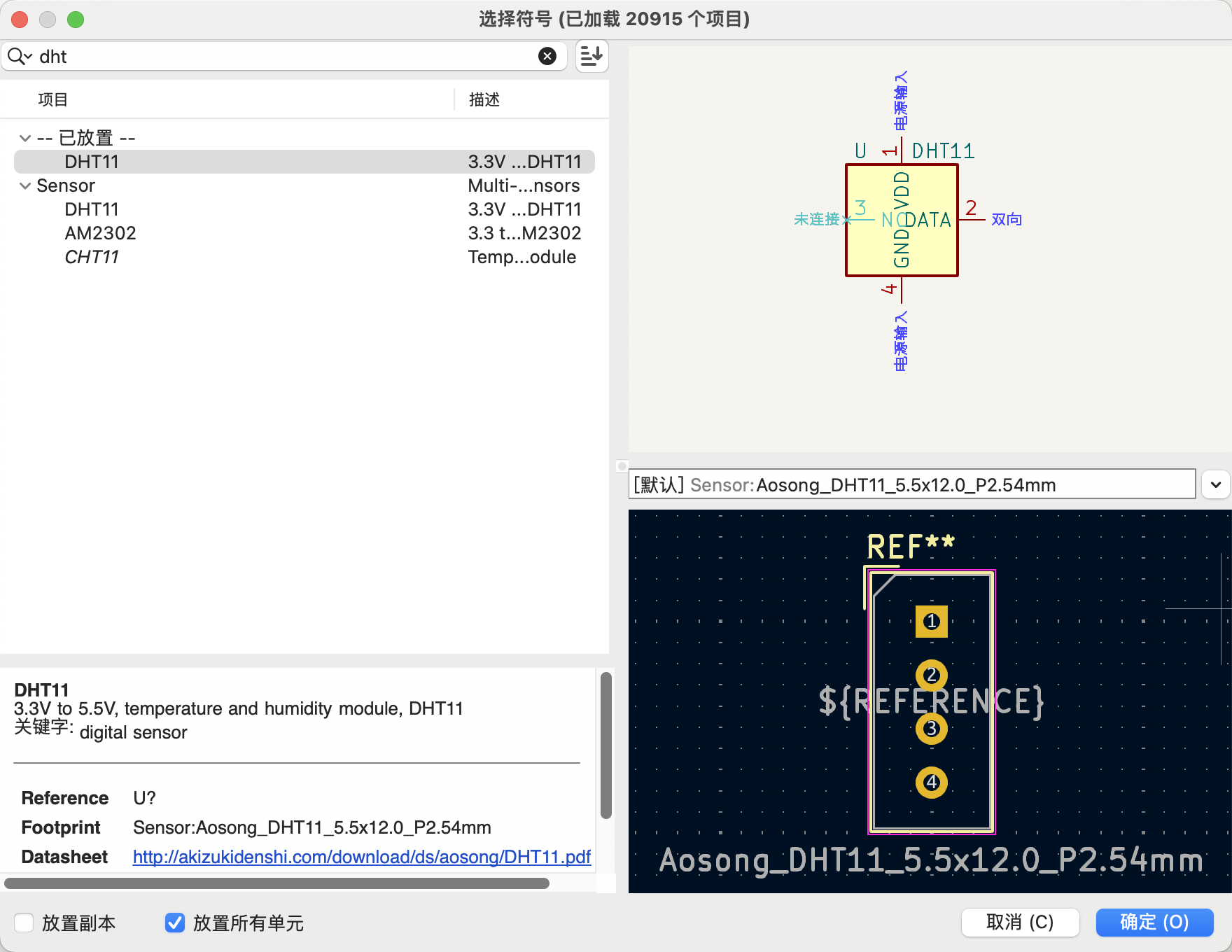
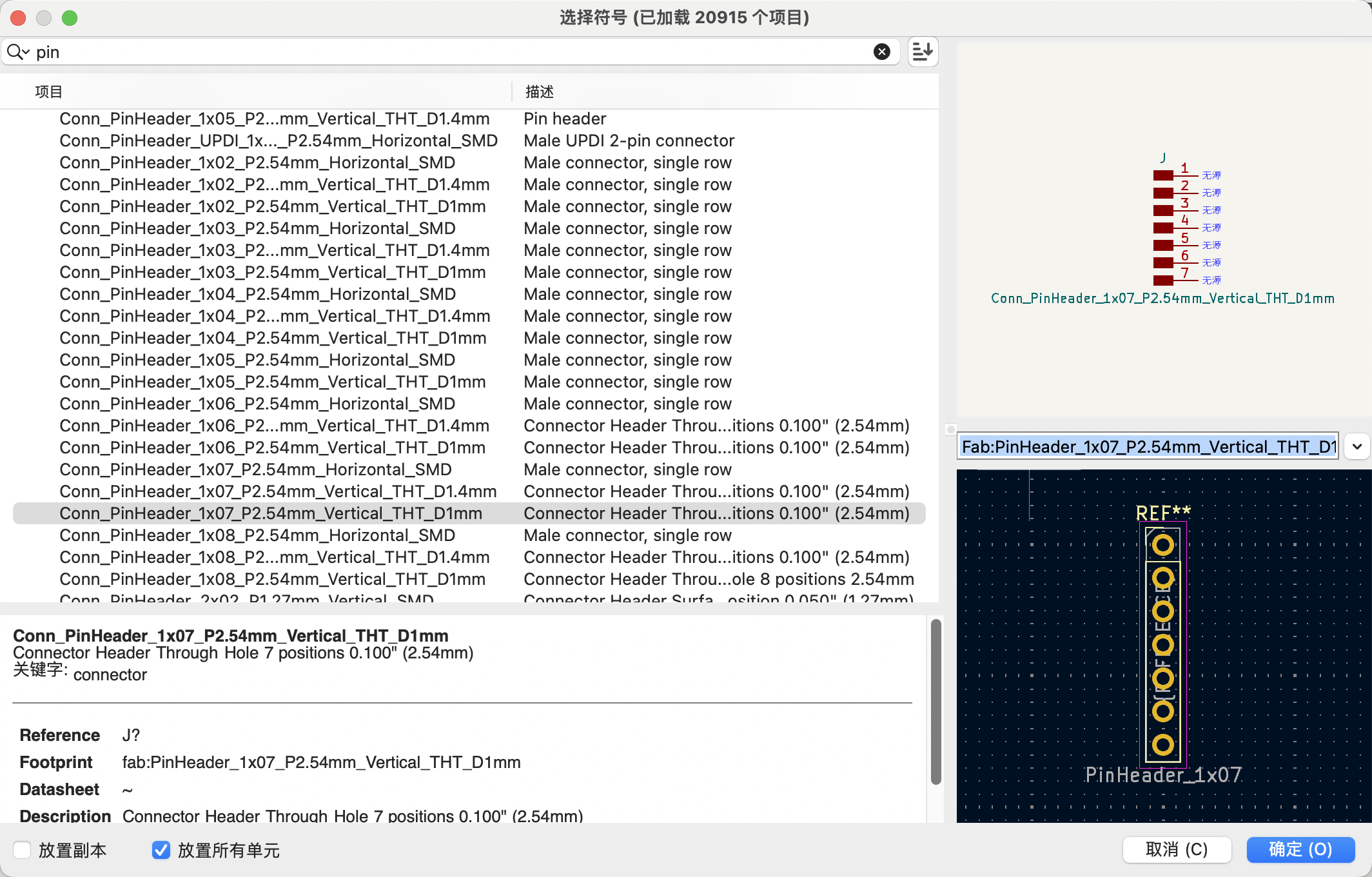
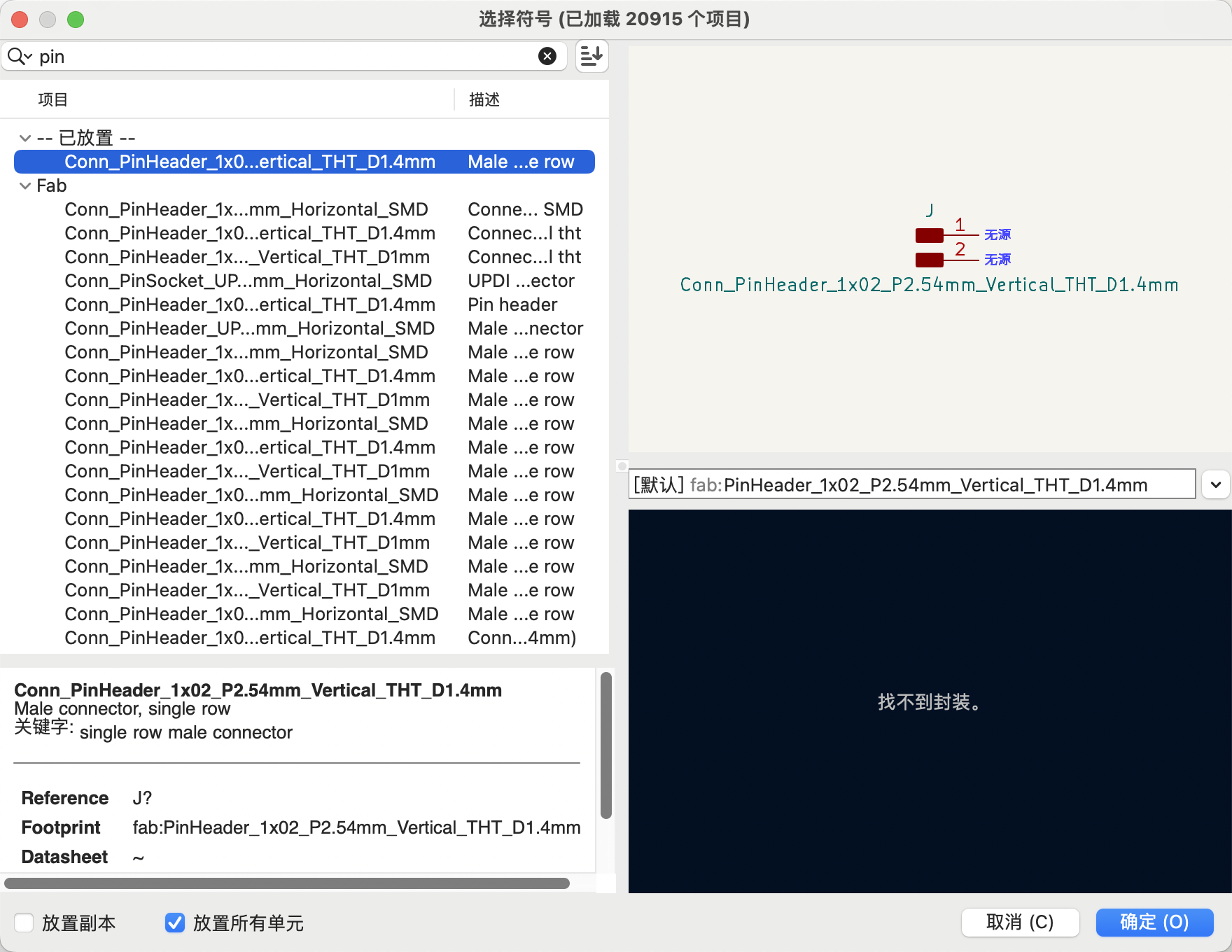
From the component library, locate the schematic symbols for the main components to be used: XiaoESP32-S3, DHT11.
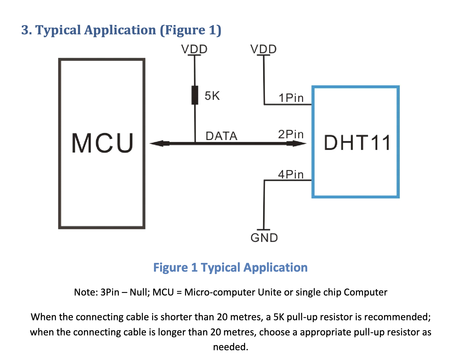
We can learn the usage information of the sensor from the datasheet.
The Data Sheet for XiaoESP32-S3:
Xiao ESP32S3 Datasheet
The Data Sheet for DHT11:
I incorporated some of the design ideas learned from the QT project into the design of the PCB for the Dao Clock.
Import the schematic symbols of the components onto the canvas.
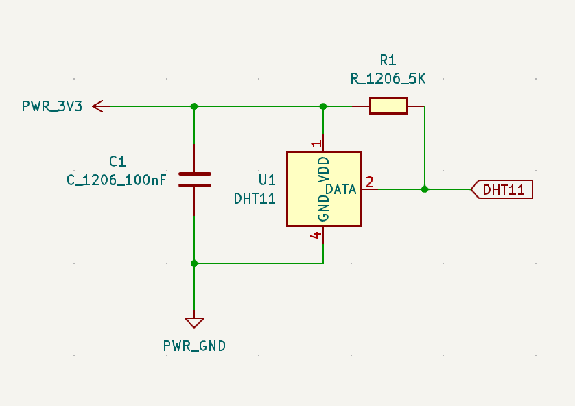
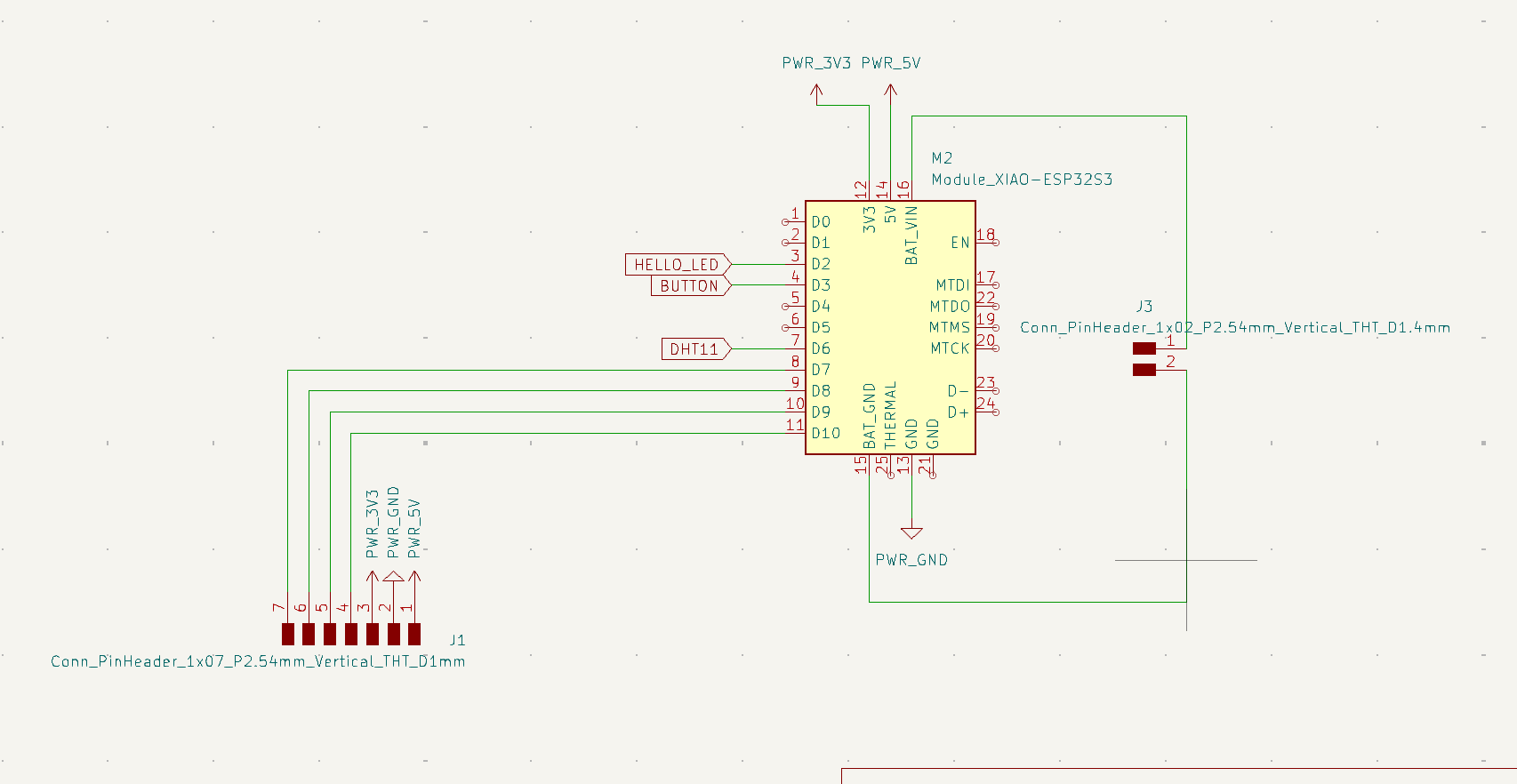
Finally,I get the schematic of the Dao Clock.
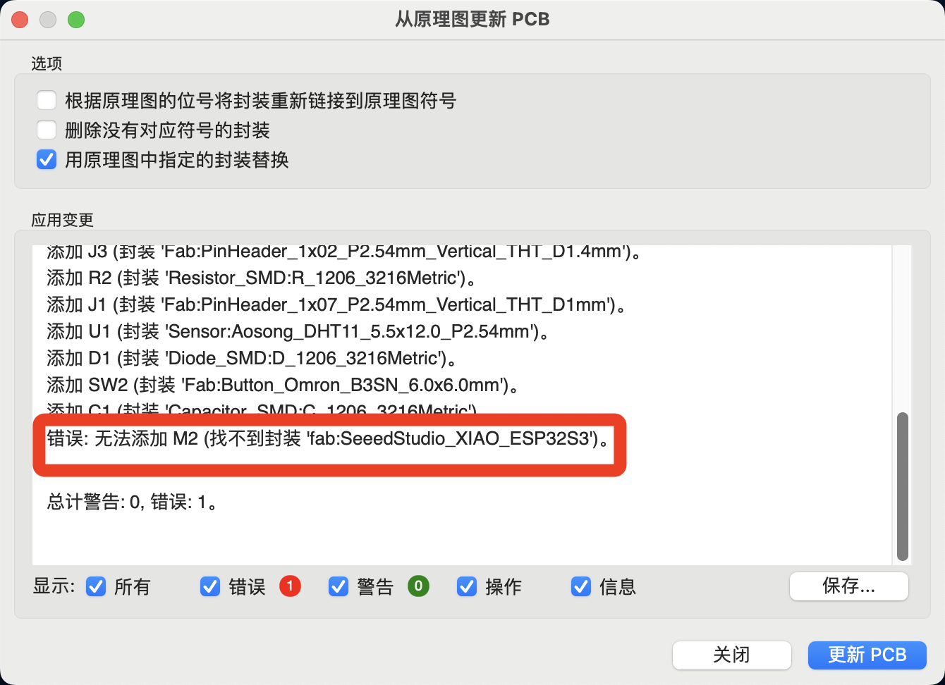
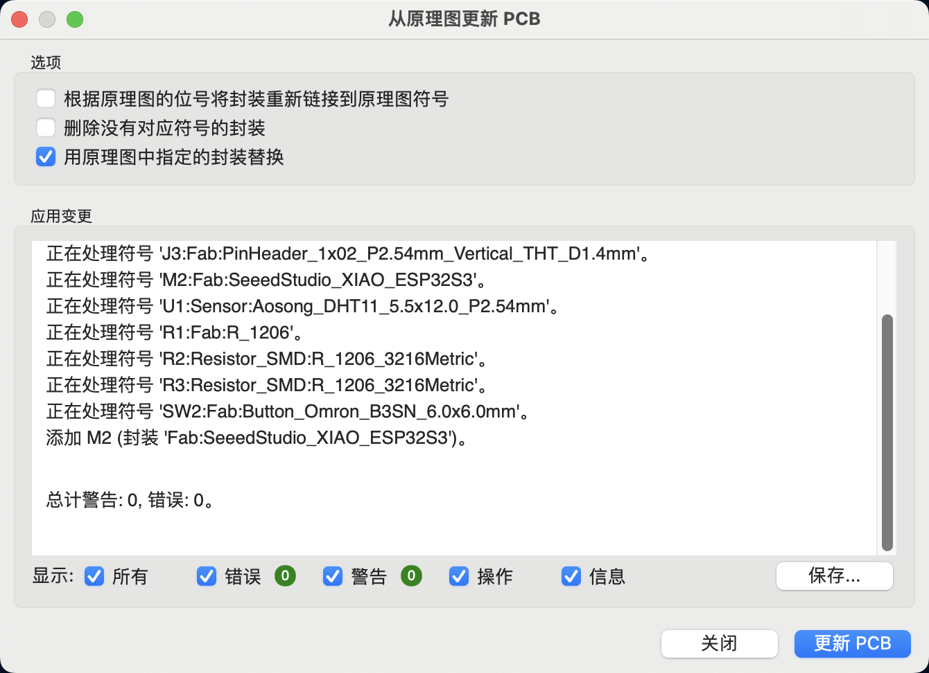
4.Design PCB files of Dao Clock
Update the PCB from the schematic.
During the conversion from schematic to PCB, a minor error occurred: I discovered that the Xiao did not have a corresponding footprint.Consequently, I went into the component editor to match the appropriate component again.
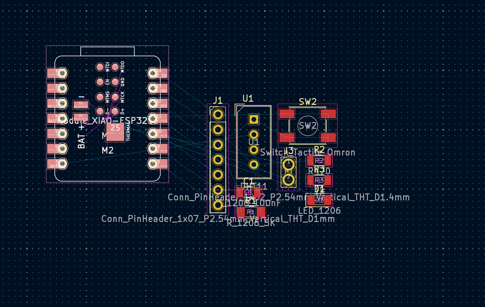
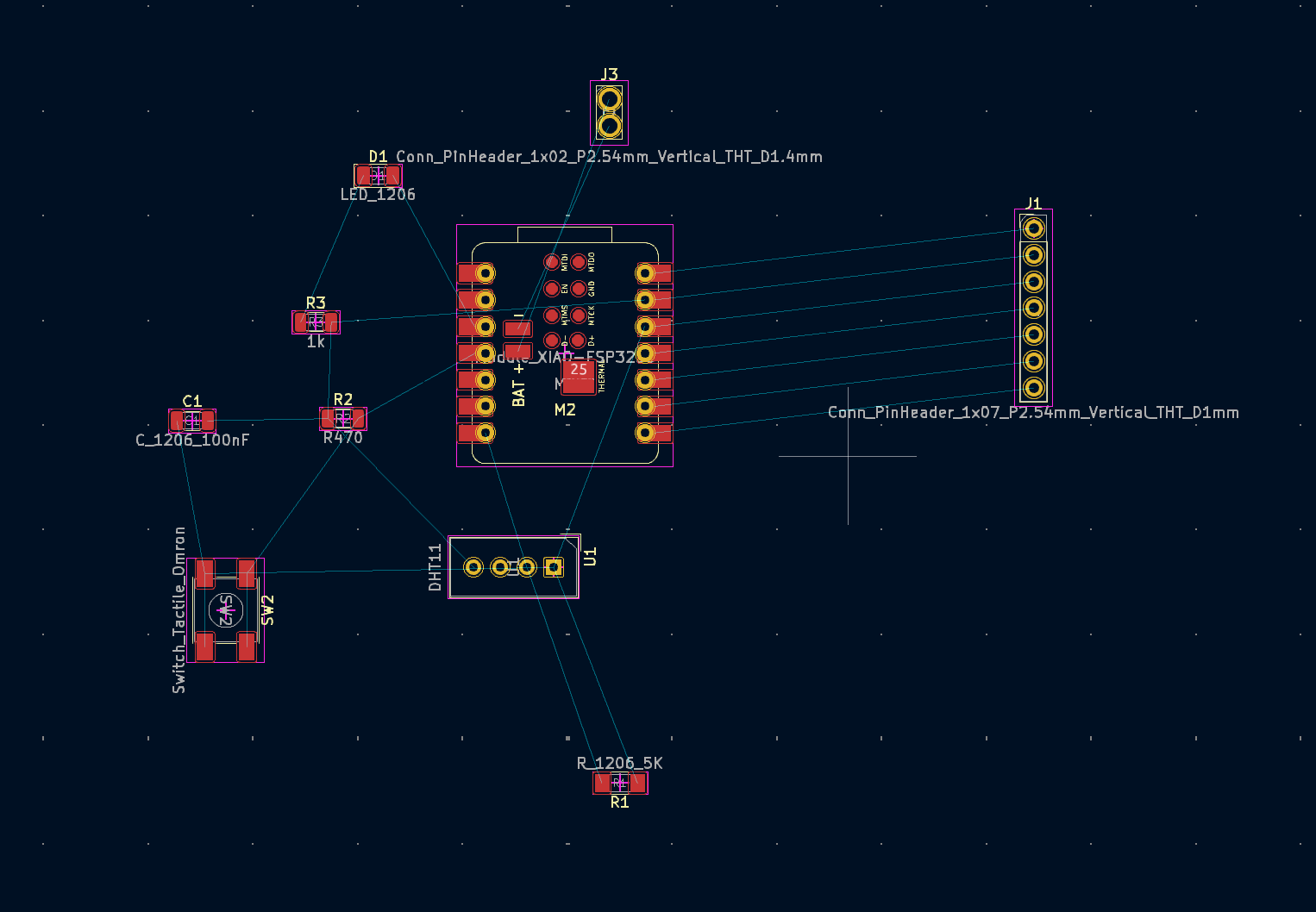
PCB Component Layout
I designed the PCB layout using the following guidelines:It also insteresting to see the final layout of the PCB.
First step is to place the components in a logical and intuitive manner.
I will first separate them to minimize the crossing of wires.
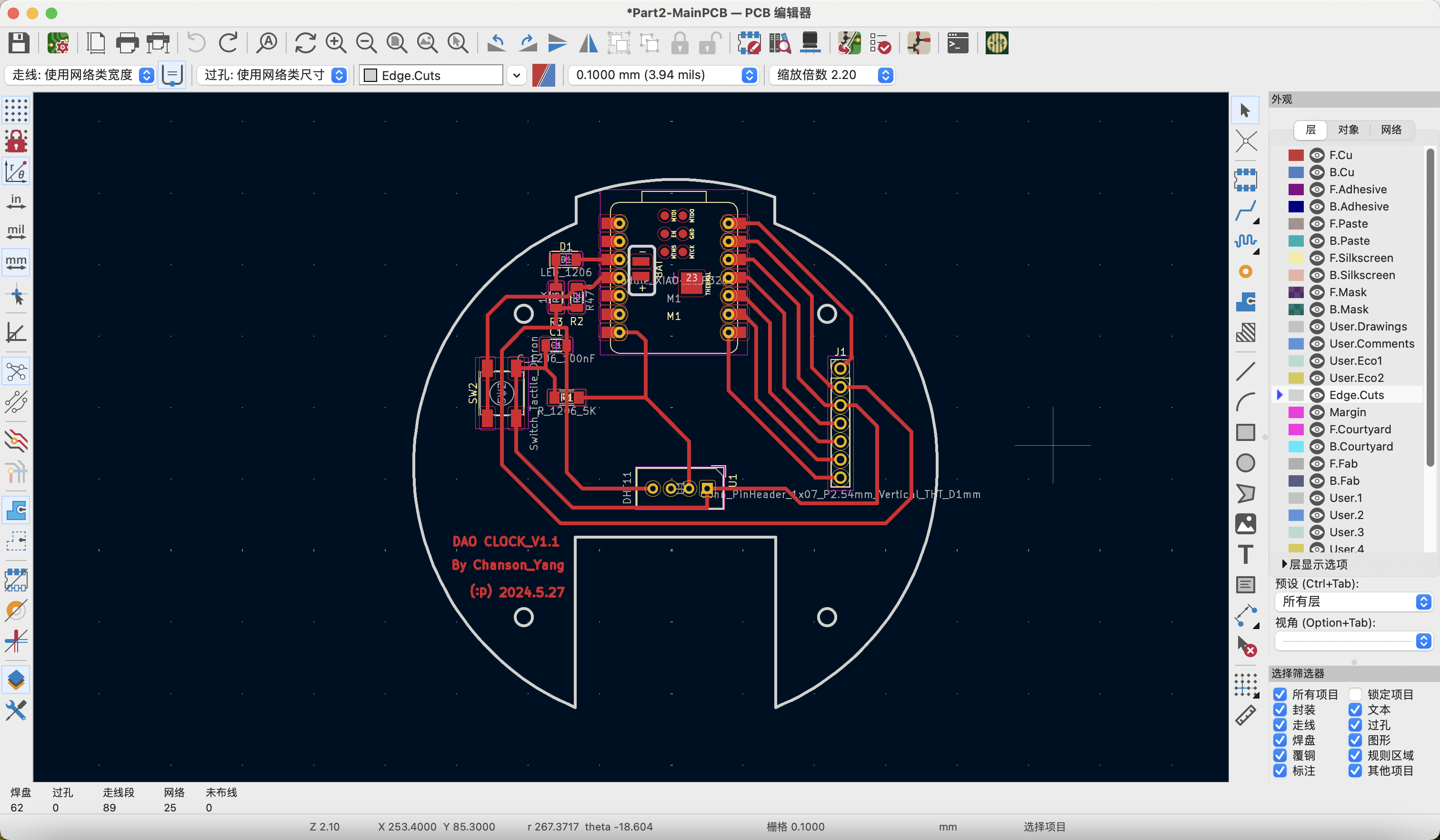
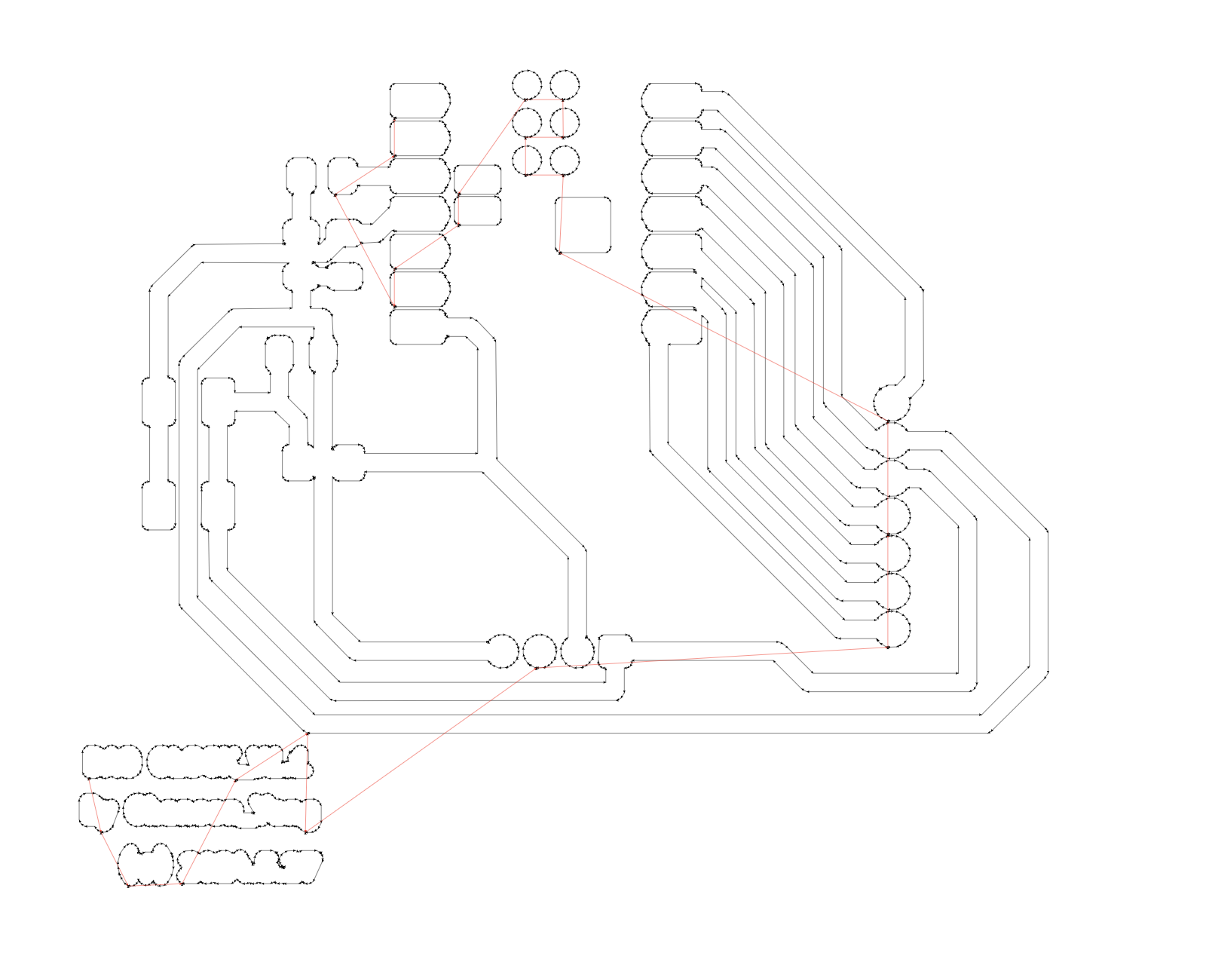
PCB Board Outline Design
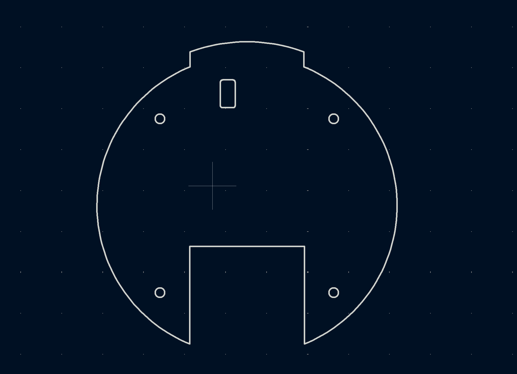
However, routing and component placement indeed require certain skills; this took up much of my time, to the extent that I kept working on it and failed to document many steps.
Ultimately, I achieved the design I wanted.
5.From Gerber to G-Code
The knowledge used in this part is the same as that in Week 4.
Converting from Gerber files to G-code files involves two steps:
1. Convert the Gerber files into recognizable PCB photoprint images.
2. Generate G-code files from the photoprint images.
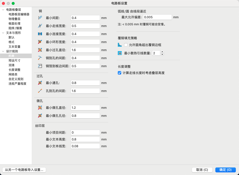
Please remember to adjust the PCB design rules, as we are using CNC machining for the PCB.
Pay attention to the minimum precision possible with CNC machining.
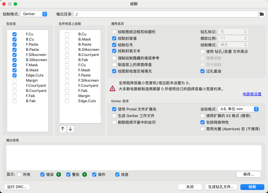
OK!We can get the manufacturing files.
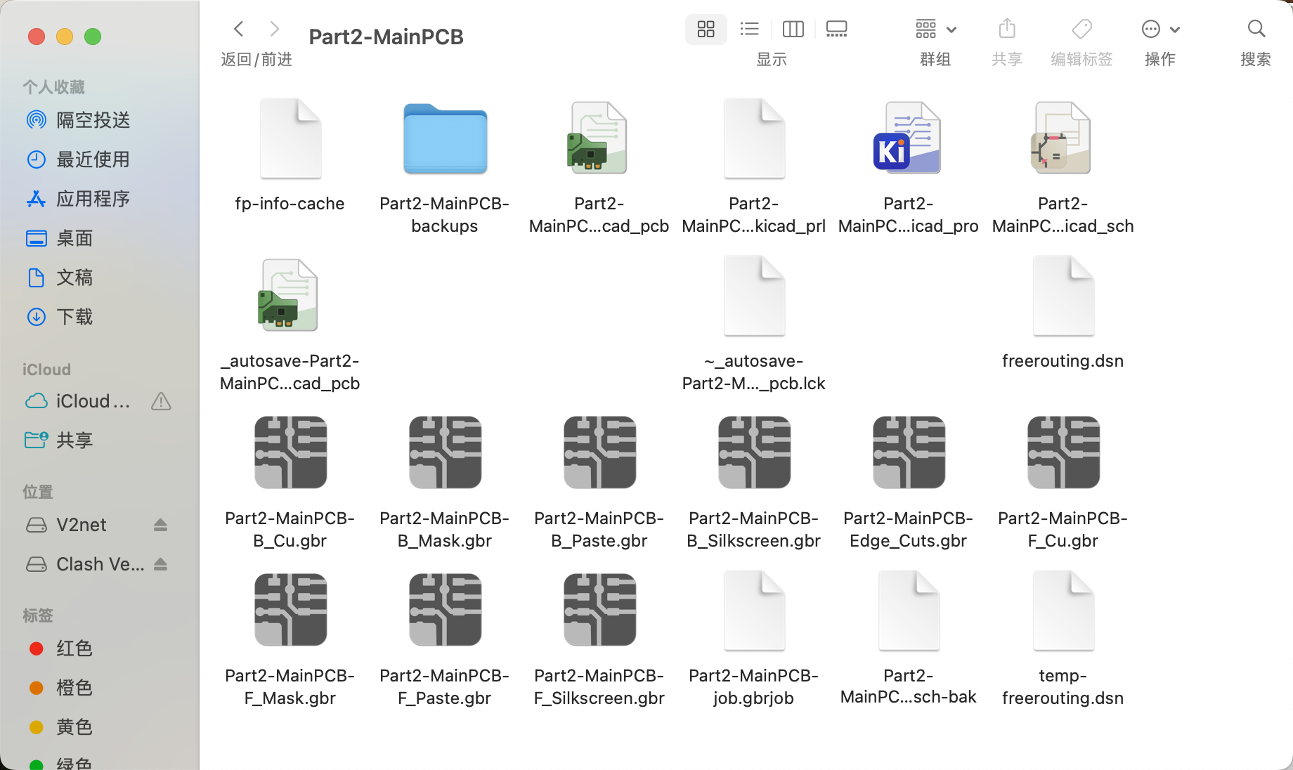
Then upload the Gerber files to the online tool Gerber2PNG to generate the PCB photoprint images.

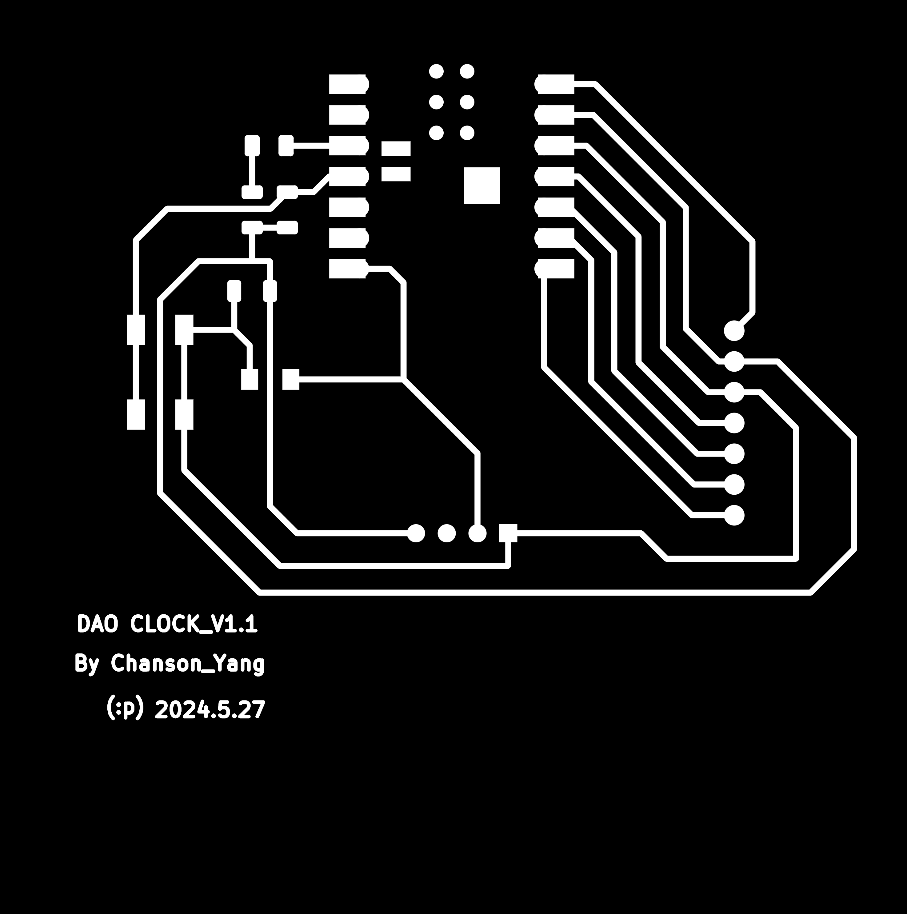
We need to get 3 images: traces, outline, and Drill.
QT PCB Photoprint images:
Traces:
Outline:
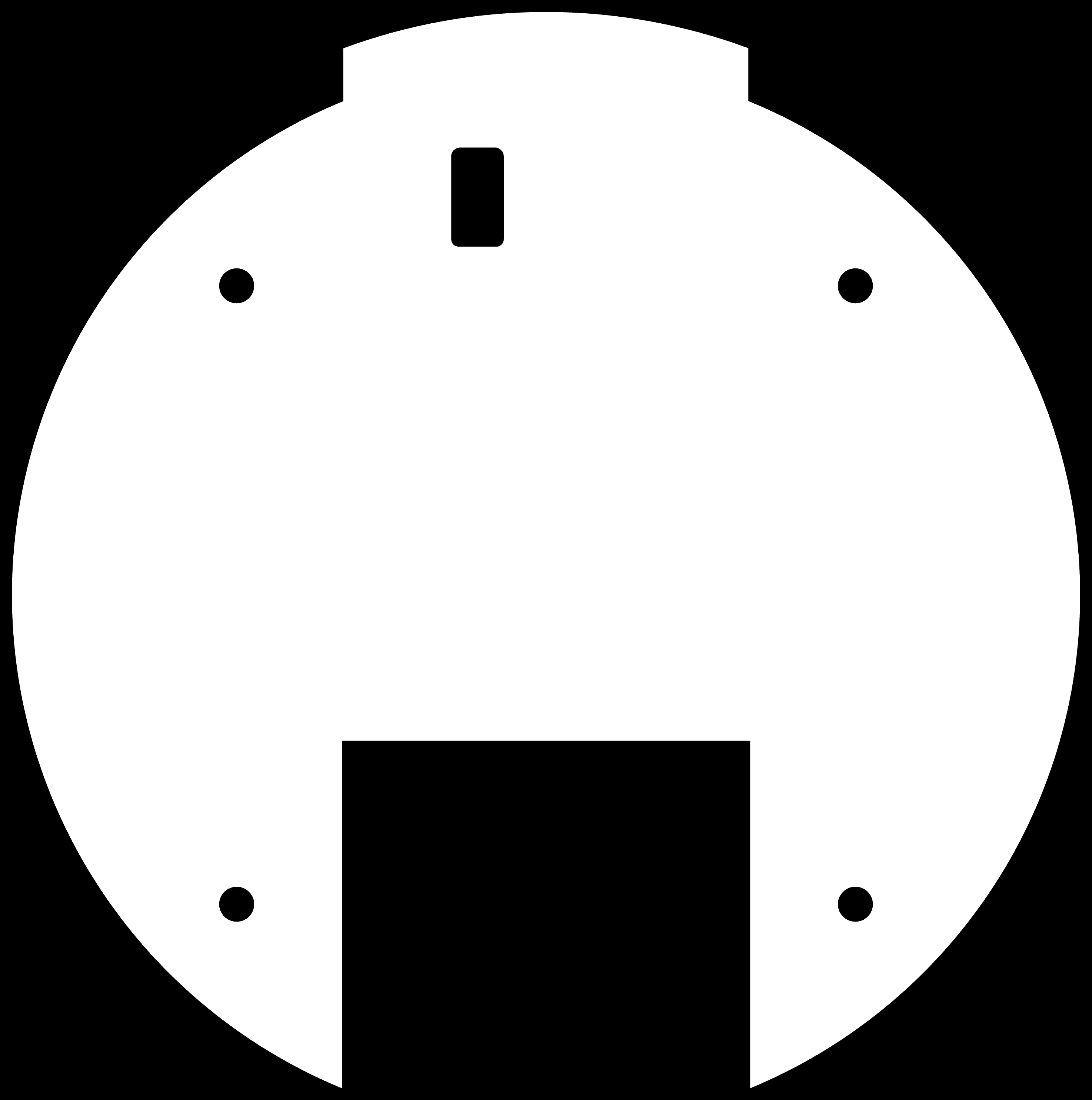
Drills:
.png)
 Special note:
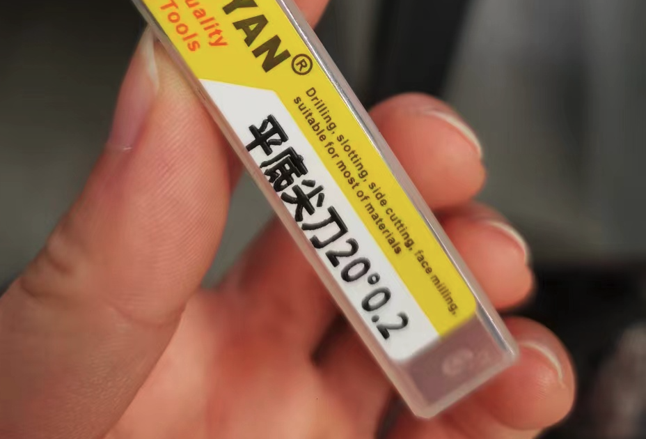
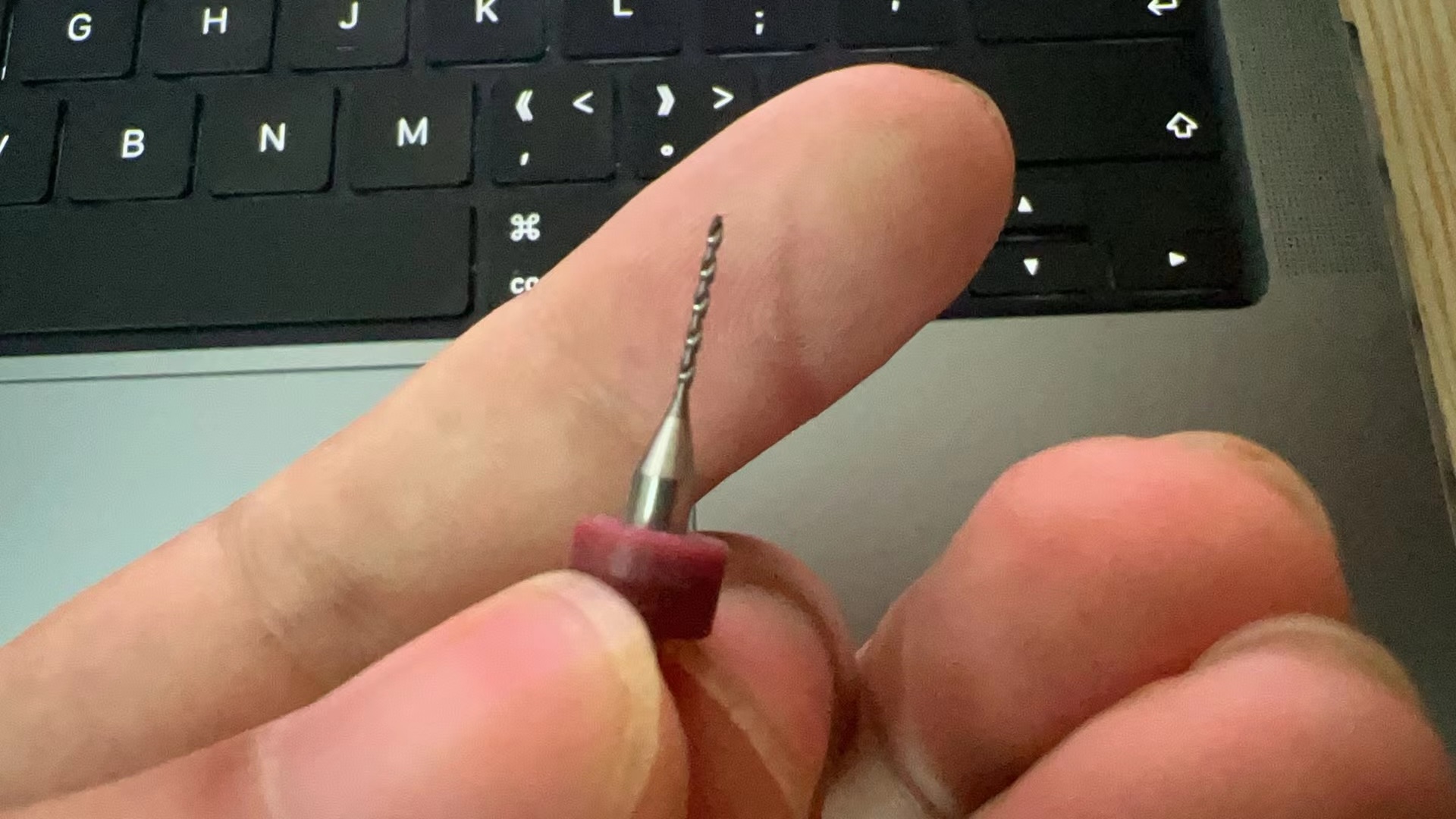
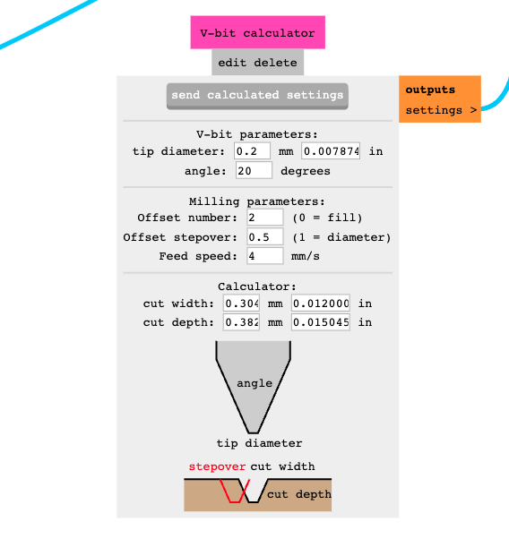
• Before setting up the machining files, please pay attention to the parameters of the engraving and drilling tools being used.
engraving tool: tip diameter--0.2mm Angle--20°
drilling tool: 0.8mm
Ultimately, we can obtain a preview of the G-code file.
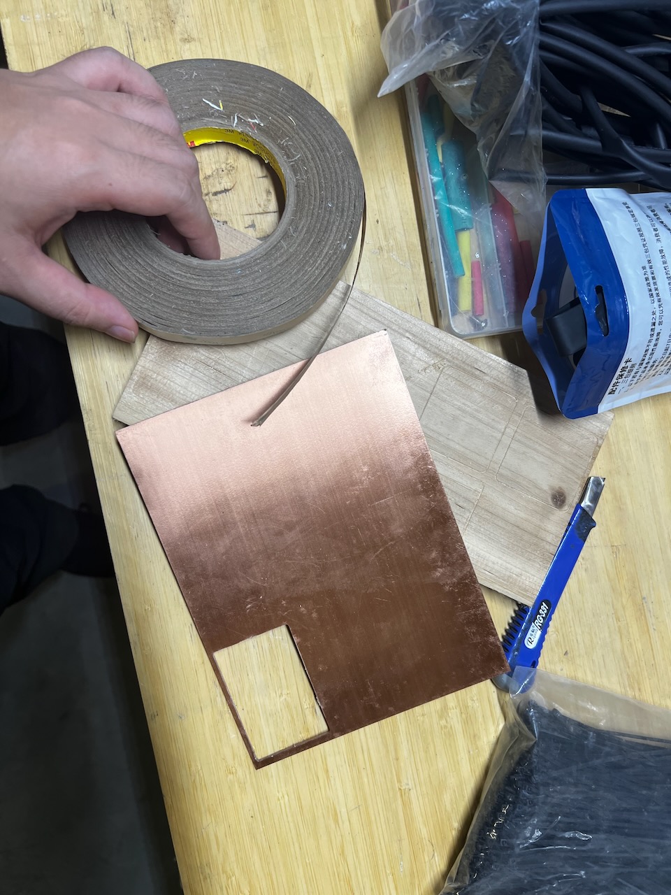
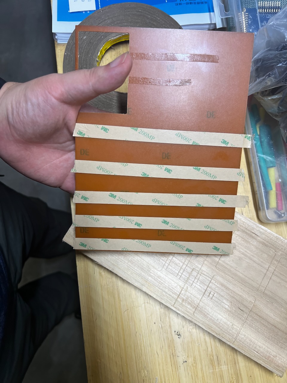
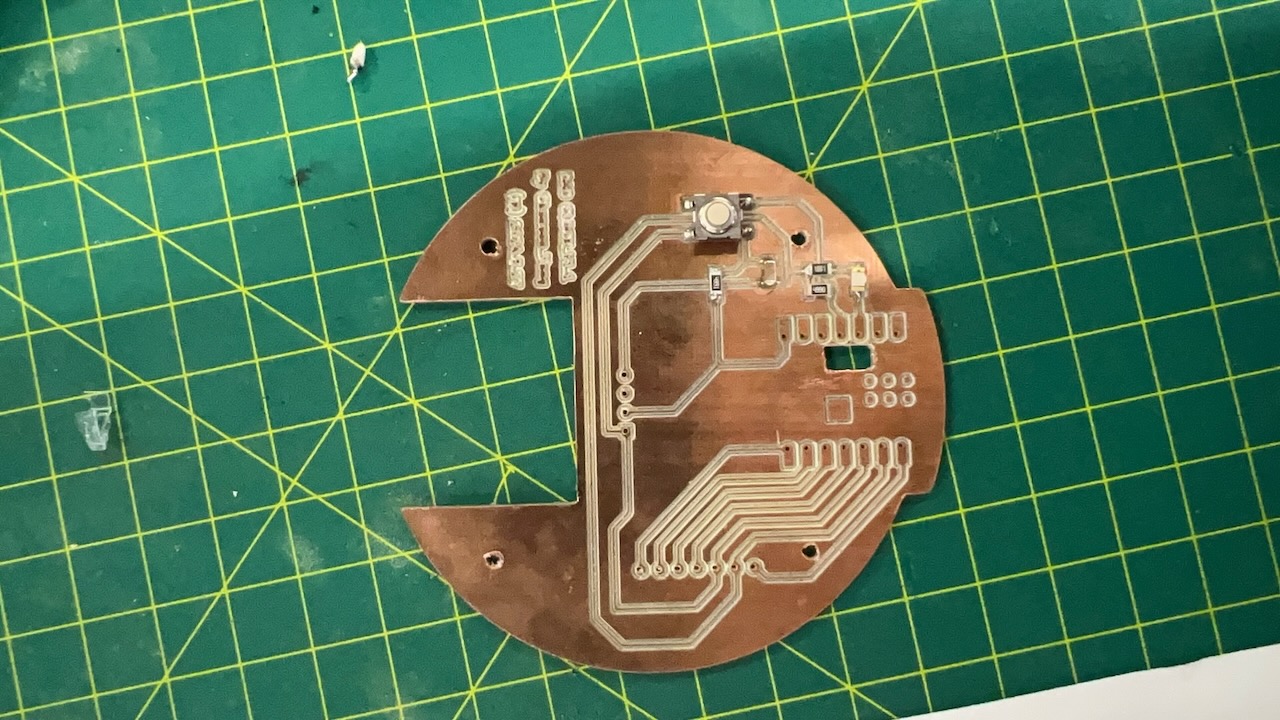
6.Machining the PCB
• Material Fixing: Use double-sided tape or a vise to secure the PCB material to be processed.
• Tool Loading: Choose appropriate V-bits or drills, mount them on the spindle, and lock them in place using the spindle wrench.
• Equipment Initialization: Use Mach3 software to power on the machine, clear alarms, and set the tool’s starting position.
• G-code Loading: Load G-code into Mach3, make final settings before machining, such as adjusting spindle speed and feed rate.
• Start Machining: Start the machine to begin processing, adjust feed rates as necessary and check the quality of machining.
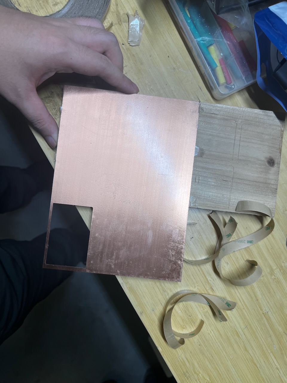


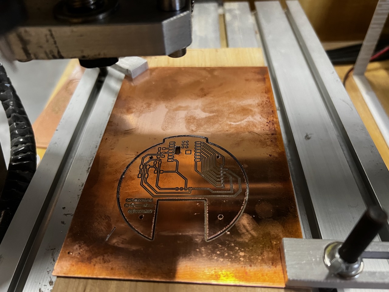
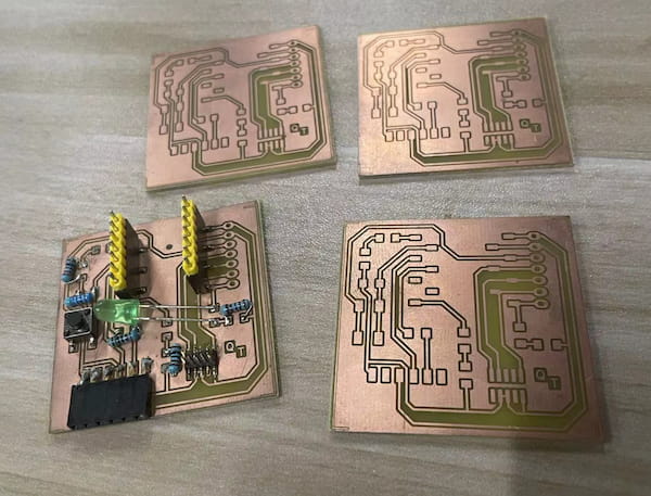
Finally, we can see the finished PCB.

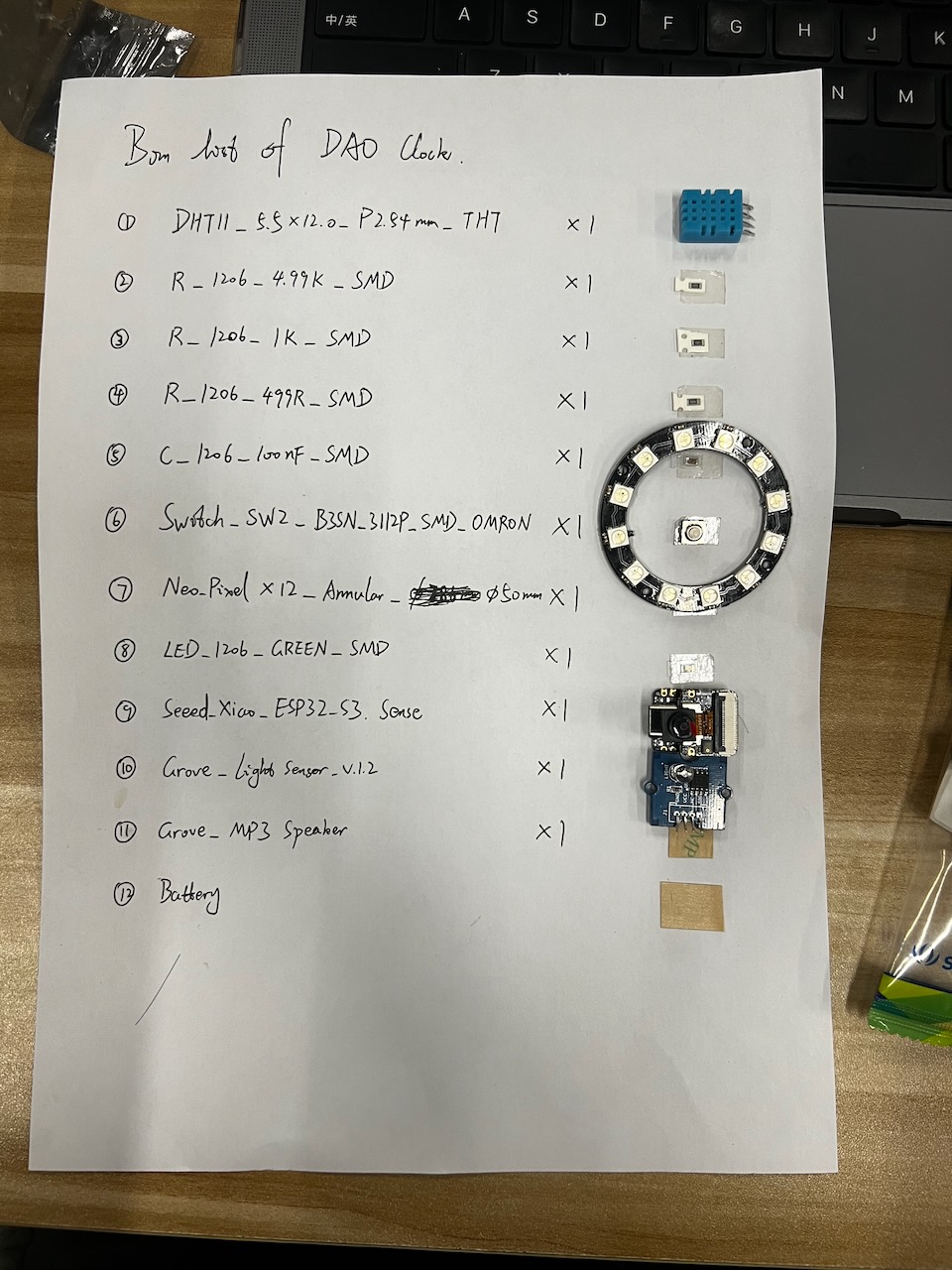
7.Make the BOM for Dao Clock PCB
After completing the PCB machining, I used a multimeter to test the connectivity of the PCB circuits to ensure there were no short circuits.
The specific method involved using the circuit connectivity test function of the multimeter, testing all the wires one by one with the positive and negative probes.
Here is the BOM (Bill of Materials) for Dao Clock.
I found each required component from the component storage area one by one, organized them together, and made a list.
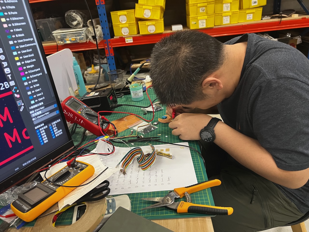
8.Solder components onto the PCB
After completing the soldering of the main components, I began soldering the Xiao ESP32-S3.
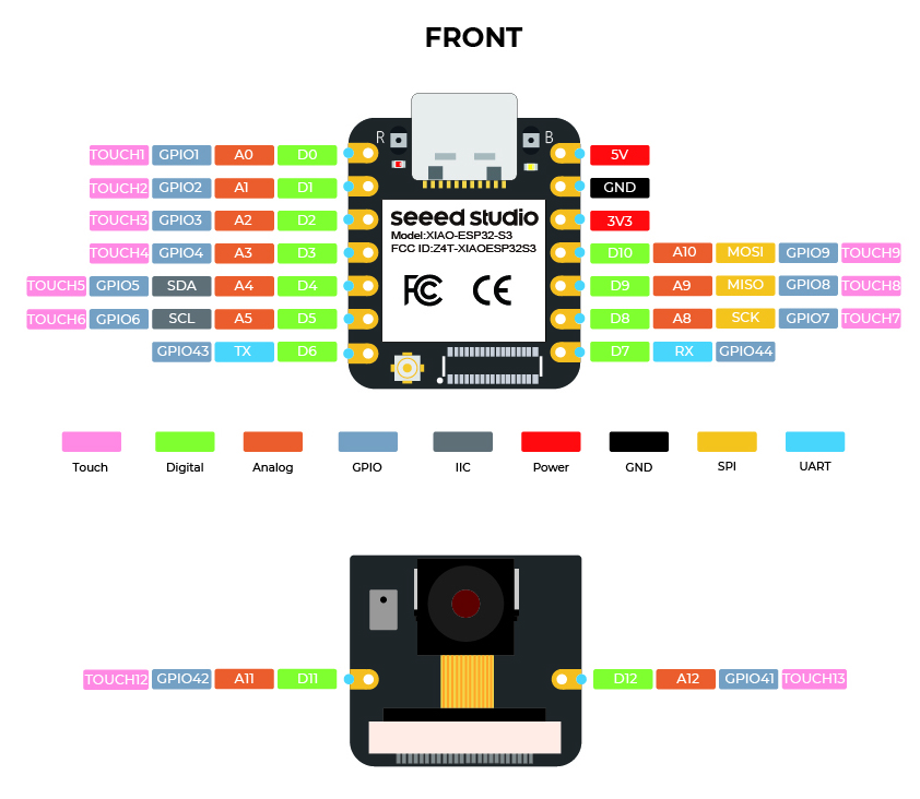
Below is the pinout manual for the Xiao ESP32-S3.
Also, be sure to place an insulating sticker at the power pin location to prevent short circuits.
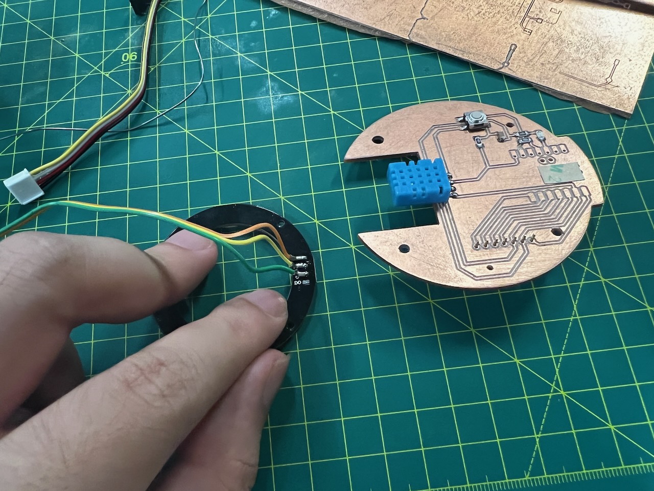
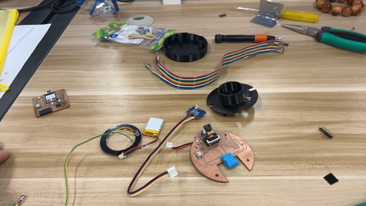
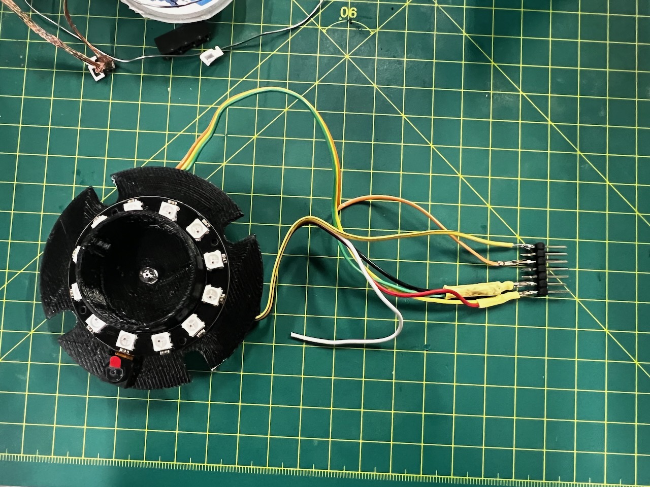
The dao clock PCB is now soldering completed.
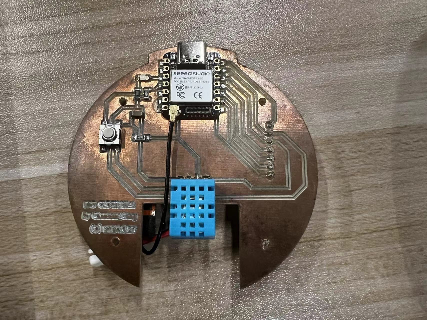
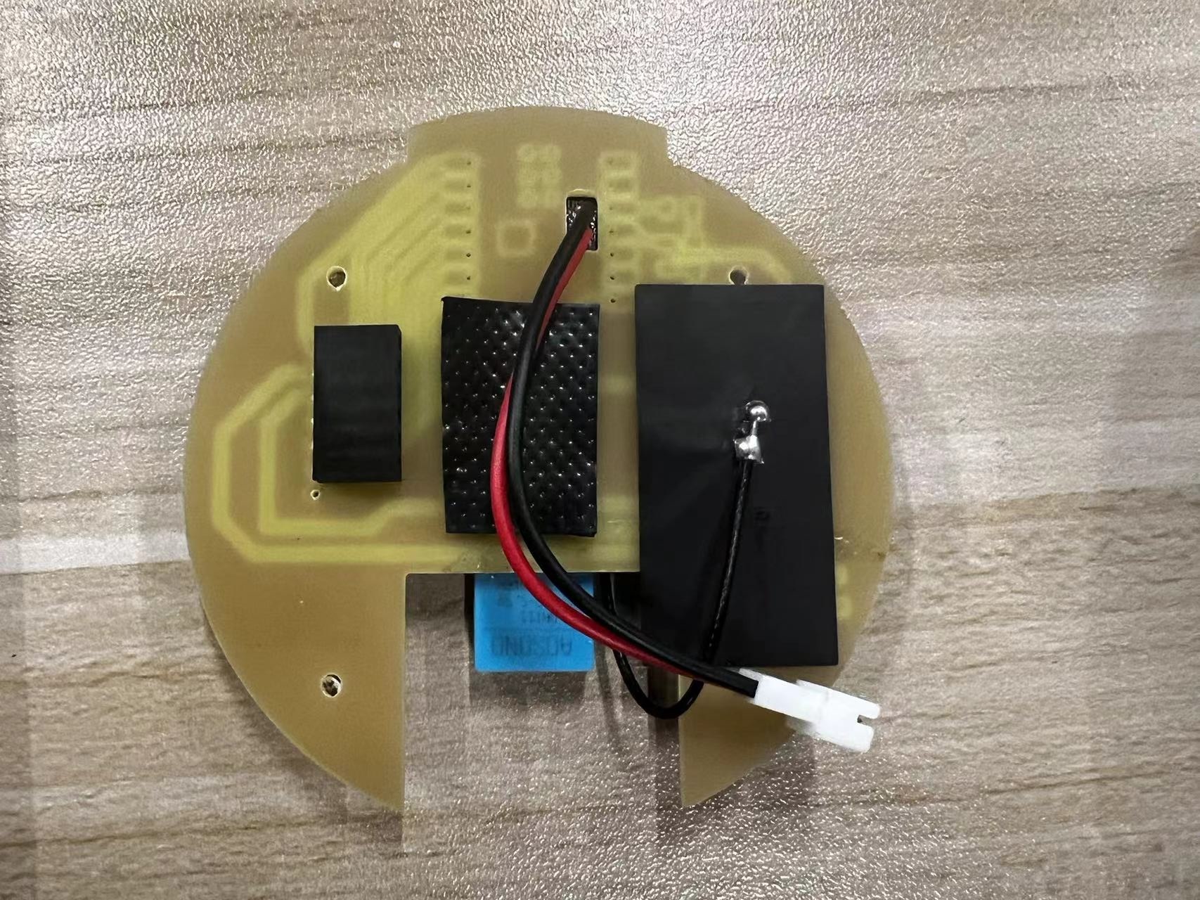
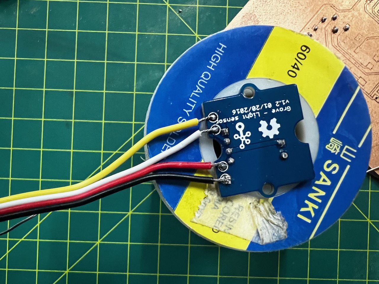
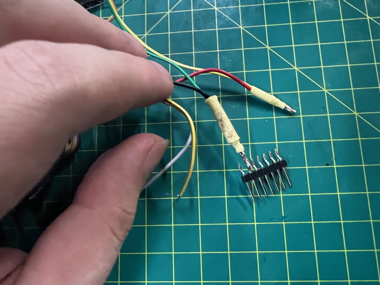
After completing this circuit board, I soldered the other components together using flying wires, including the photoresistor and the Neopixels ring.
9.Some Problems and Solutions.
When I completed my first PCB design, I was the fastest progressing member in our group.
However, during the subsequent program testing, I found that the DHT11 was not functioning properly, and I smelled something burning.
I realized there must have been a short circuit somewhere.
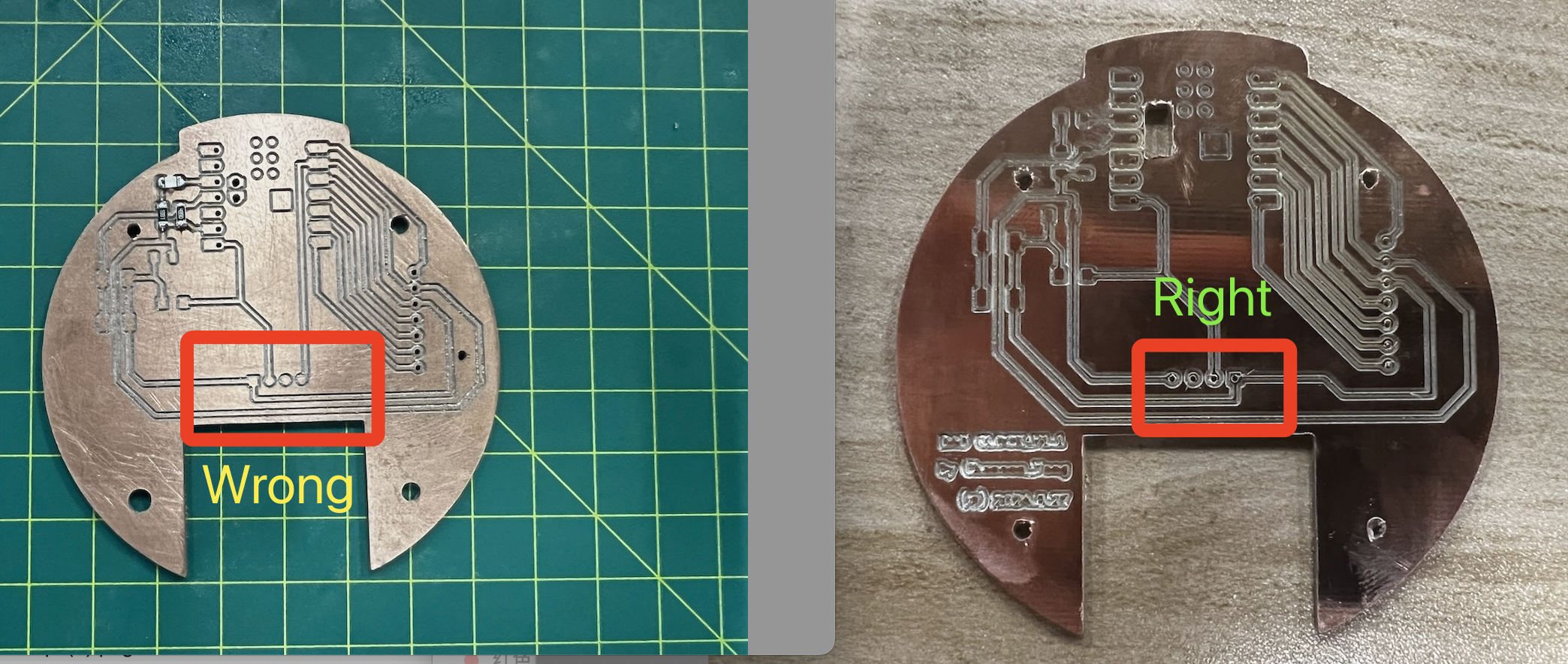
After attempting to troubleshoot many times and burning out another DHT11 sensor, I discovered that a flaw in the circuit board design had caused me to connect the pins incorrectly, thereby damaging the DHT11 component.
The circuit board I showed earlier is the correctly adjusted final design.
Now, I'm also sharing the failed version.
This reminds me to carefully and meticulously review the component datasheets to ensure correct installation.
10.Test the PCB.
After completing the entire PCBA, I chose to use a Neopixels Demo program code to test whether this PCBA is functional.• PIN_NEOPIXEL (D9): This GPIO pin D9 is designated for connecting NeoPixel LEDs, controlling a string of 12 pixels for display or signaling purposes.
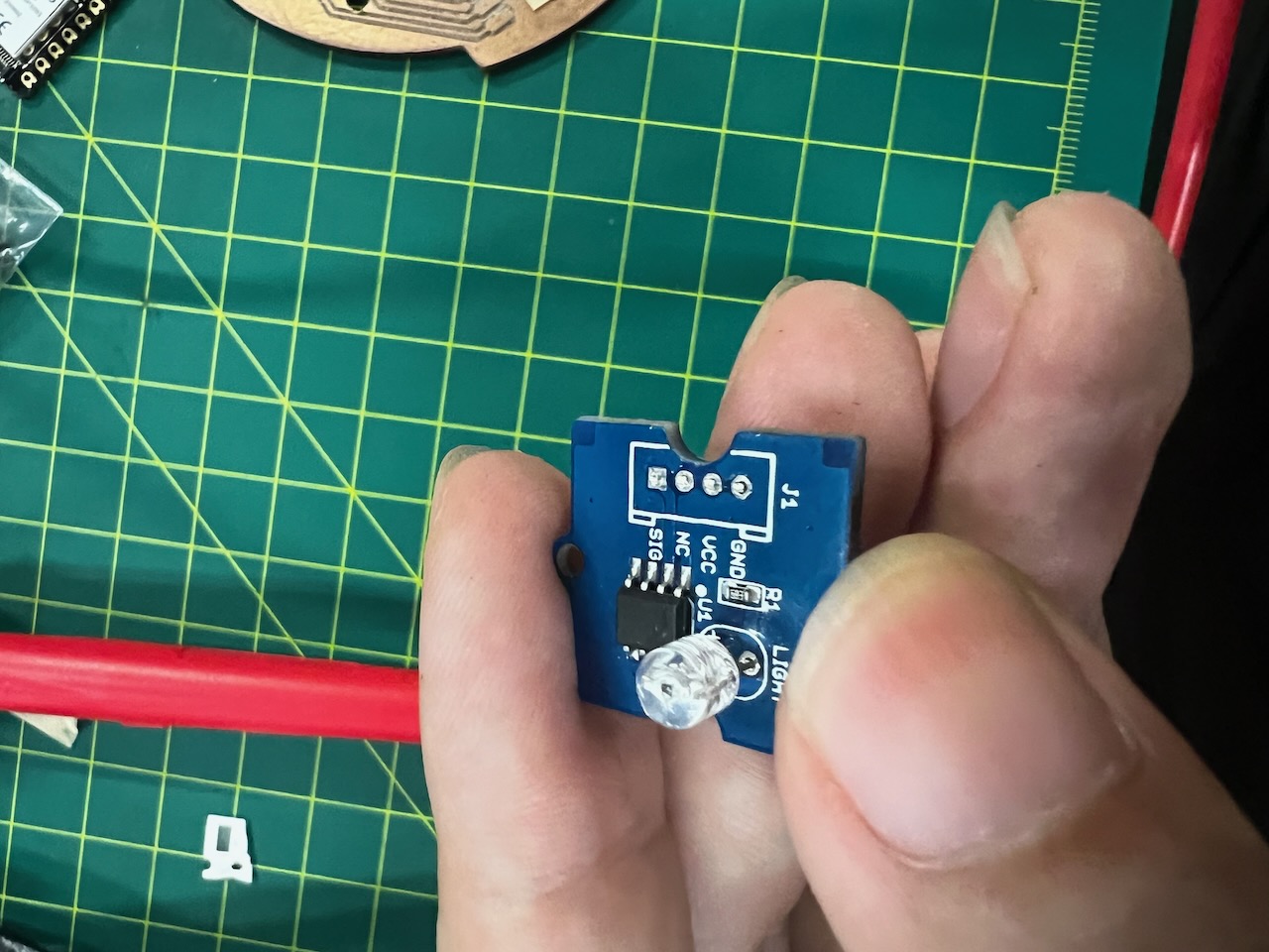
• LIGHT_SENSOR_PIN (A8): The analog input pin A8 is used to connect a light sensor, which measures light intensity for environmental monitoring or responsive actions.
• DHTPIN (D6): This GPIO pin D6 is allocated for the DHT11 sensor, which measures temperature and humidity, essential for environmental data gathering in your project.
Here is my code:
#include
#include "Grove_Temperature_And_Humidity_Sensor.h"
#ifdef __AVR__
#include // Required for 16 MHz Adafruit Trinket
#endif
// Which pin on the Arduino is connected to the NeoPixels?
#define PIN D9 // On Trinket or Gemma, suggest changing this to 1
// How many NeoPixels are attached to the Arduino?
#define LED_COUNT 12 // Popular NeoPixel ring size
// When setting up the NeoPixel library, we tell it how many pixels,
// and which pin to use to send signals. Note that for older NeoPixel
// strips you might need to change the third parameter -- see the
// strandtest example for more information on possible values.
Adafruit_NeoPixel strip(LED_COUNT, PIN, NEO_GRB + NEO_KHZ800);
#define DELAYVAL 500 // Time (in milliseconds) to pause between pixels
#define DHTTYPE DHT11 // DHT 11
#define DHTPIN D6 // what pin we're connected to(DHT10 and DHT20 don't need define it)
DHT dht(DHTPIN, DHTTYPE); // DHT11 DHT21 DHT22
#if defined(ARDUINO_ARCH_AVR)
#define debug Serial
#elif defined(ARDUINO_ARCH_SAMD) || defined(ARDUINO_ARCH_SAM)
#define debug SerialUSB
#else
#define debug Serial
#endif
int sensorpin = A8; // Analog input pin that the sensor is attached to
int sensorValue = 0; // value read from the port
int outputValue = 0; // value output to the PWM (analog out)
void setup() {
// These lines are specifically to support the Adafruit Trinket 5V 16 MHz.
// Any other board, you can remove this part (but no harm leaving it):
#if defined(__AVR_ATtiny85__) && (F_CPU == 16000000)
clock_prescale_set(clock_div_1);
#endif
strip.begin(); // INITIALIZE NeoPixel strip object (REQUIRED)
strip.show(); // Turn OFF all pixels ASAP
strip.setBrightness(10); // Set BRIGHTNESS to about 1/5 (max = 255)
// END of Trinket-specific code.
debug.begin(115200);
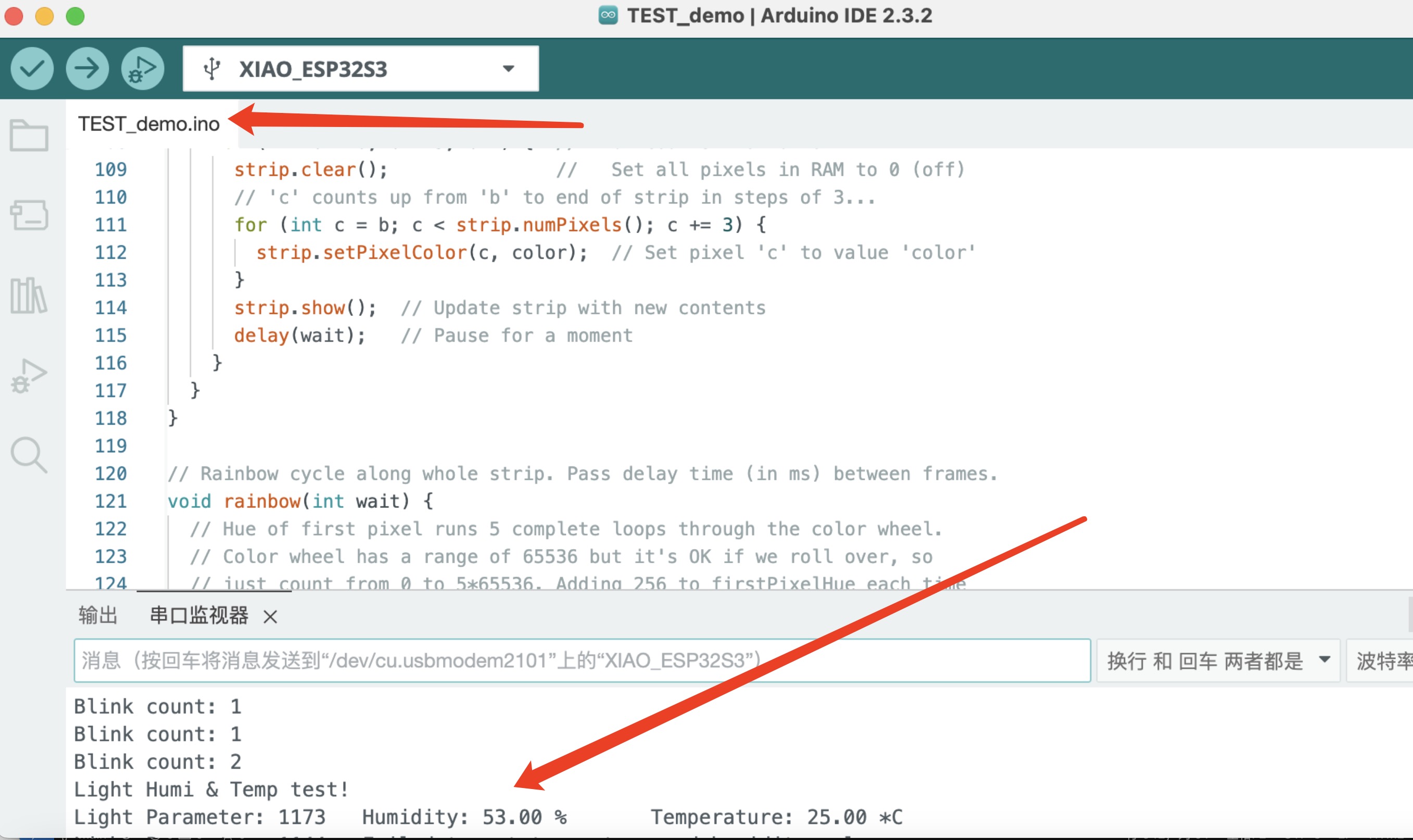
debug.println("Light Humi & Temp test!");
Wire.begin();
pinMode(sensorpin, INPUT);
Serial.begin(115200);
}
void loop() {
// The first NeoPixel in a strand is #0, second is 1, all the way up
// to the count of pixels minus one.
// Fill along the length of the strip in various colors...
colorWipe(strip.Color(255, 0, 0), 10); // Red
colorWipe(strip.Color(0, 255, 0), 10); // Green
colorWipe(strip.Color(0, 0, 255), 10); // Blue
// Do a theater marquee effect in various colors...
theaterChase(strip.Color(127, 127, 127), 10); // White, half brightness
theaterChase(strip.Color(127, 0, 0), 10); // Red, half brightness
theaterChase(strip.Color(0, 0, 127), 10); // Blue, half brightness
rainbow(10); // Flowing rainbow cycle along the whole strip
theaterChaseRainbow(50); // Rainbow-enhanced theaterChase variant
sensorValue = analogRead(sensorpin);
debug.print("Light Parameter: ");
debug.print(sensorValue);
debug.print("\t");
float temp_hum_val[2] = { 0 };
// Reading temperature or humidity takes about 250 milliseconds!
// Sensor readings may also be up to 2 seconds 'old' (its a very slow sensor)
if (!dht.readTempAndHumidity(temp_hum_val)) {
debug.print("Humidity: ");
debug.print(temp_hum_val[0]);
debug.print(" %\t");
debug.print("Temperature: ");
debug.print(temp_hum_val[1]);
debug.println(" *C");
} else {
debug.println("Failed to get temprature and humidity value.");
}
delay(200);
}
void colorWipe(uint32_t color, int wait) {
for (int i = 0; i < strip.numPixels(); i++) { // For each pixel in strip...
strip.setPixelColor(i, color); // Set pixel's color (in RAM)
strip.show(); // Update strip to match
delay(wait); // Pause for a moment
}
}
// Theater-marquee-style chasing lights. Pass in a color (32-bit value,
// a la strip.Color(r,g,b) as mentioned above), and a delay time (in ms)
// between frames.
void theaterChase(uint32_t color, int wait) {
for (int a = 0; a < 10; a++) { // Repeat 10 times...
for (int b = 0; b < 3; b++) { // 'b' counts from 0 to 2...
strip.clear(); // Set all pixels in RAM to 0 (off)
// 'c' counts up from 'b' to end of strip in steps of 3...
for (int c = b; c < strip.numPixels(); c += 3) {
strip.setPixelColor(c, color); // Set pixel 'c' to value 'color'
}
strip.show(); // Update strip with new contents
delay(wait); // Pause for a moment
}
}
}
// Rainbow cycle along whole strip. Pass delay time (in ms) between frames.
void rainbow(int wait) {
// Hue of first pixel runs 5 complete loops through the color wheel.
// Color wheel has a range of 65536 but it's OK if we roll over, so
// just count from 0 to 5*65536. Adding 256 to firstPixelHue each time
// means we'll make 5*65536/256 = 1280 passes through this loop:
for (long firstPixelHue = 0; firstPixelHue < 5 * 65536; firstPixelHue += 256) {
// strip.rainbow() can take a single argument (first pixel hue) or
// optionally a few extras: number of rainbow repetitions (default 1),
// saturation and value (brightness) (both 0-255, similar to the
// ColorHSV() function, default 255), and a true/false flag for whether
// to apply gamma correction to provide 'truer' colors (default true).
strip.rainbow(firstPixelHue);
// Above line is equivalent to:
// strip.rainbow(firstPixelHue, 1, 255, 255, true);
strip.show(); // Update strip with new contents
delay(wait); // Pause for a moment
}
}
// Rainbow-enhanced theater marquee. Pass delay time (in ms) between frames.
void theaterChaseRainbow(int wait) {
int firstPixelHue = 0; // First pixel starts at red (hue 0)
for (int a = 0; a < 30; a++) { // Repeat 30 times...
for (int b = 0; b < 3; b++) { // 'b' counts from 0 to 2...
strip.clear(); // Set all pixels in RAM to 0 (off)
// 'c' counts up from 'b' to end of strip in increments of 3...
for (int c = b; c < strip.numPixels(); c += 3) {
// hue of pixel 'c' is offset by an amount to make one full
// revolution of the color wheel (range 65536) along the length
// of the strip (strip.numPixels() steps):
int hue = firstPixelHue + c * 65536L / strip.numPixels();
uint32_t color = strip.gamma32(strip.ColorHSV(hue)); // hue -> RGB
strip.setPixelColor(c, color); // Set pixel 'c' to value 'color'
}
strip.show(); // Update strip with new contents
delay(wait); // Pause for a moment
firstPixelHue += 65536 / 90; // One cycle of color wheel over 90 frames
}
}
}
OK, now let's test the PCB.
11.The Hero Shots
A photo from 6 AM, after a sleepless night.

Team Assignment
Week8 Electronics Design Group Assignment link.
Oscilloscope
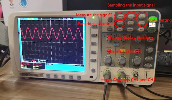
An oscilloscope is a crucial tool in electronics, enabling the visualization of electrical signal voltages as waveforms over time.
It offers various features:
• **Display:** Shows electrical signals as waveforms, with voltage on the vertical axis and time on the horizontal axis.
• **Channels:** Allows multiple signals to be viewed simultaneously.
• **Bandwidth:** Determines the frequency range the oscilloscope can measure accurately.
• **Sampling Rate:** The rate at which the oscilloscope samples the signal, crucial for capturing fast-changing signals.
• **Triggering:** Stabilizes repeating signals by starting data capture at a specific signal point.

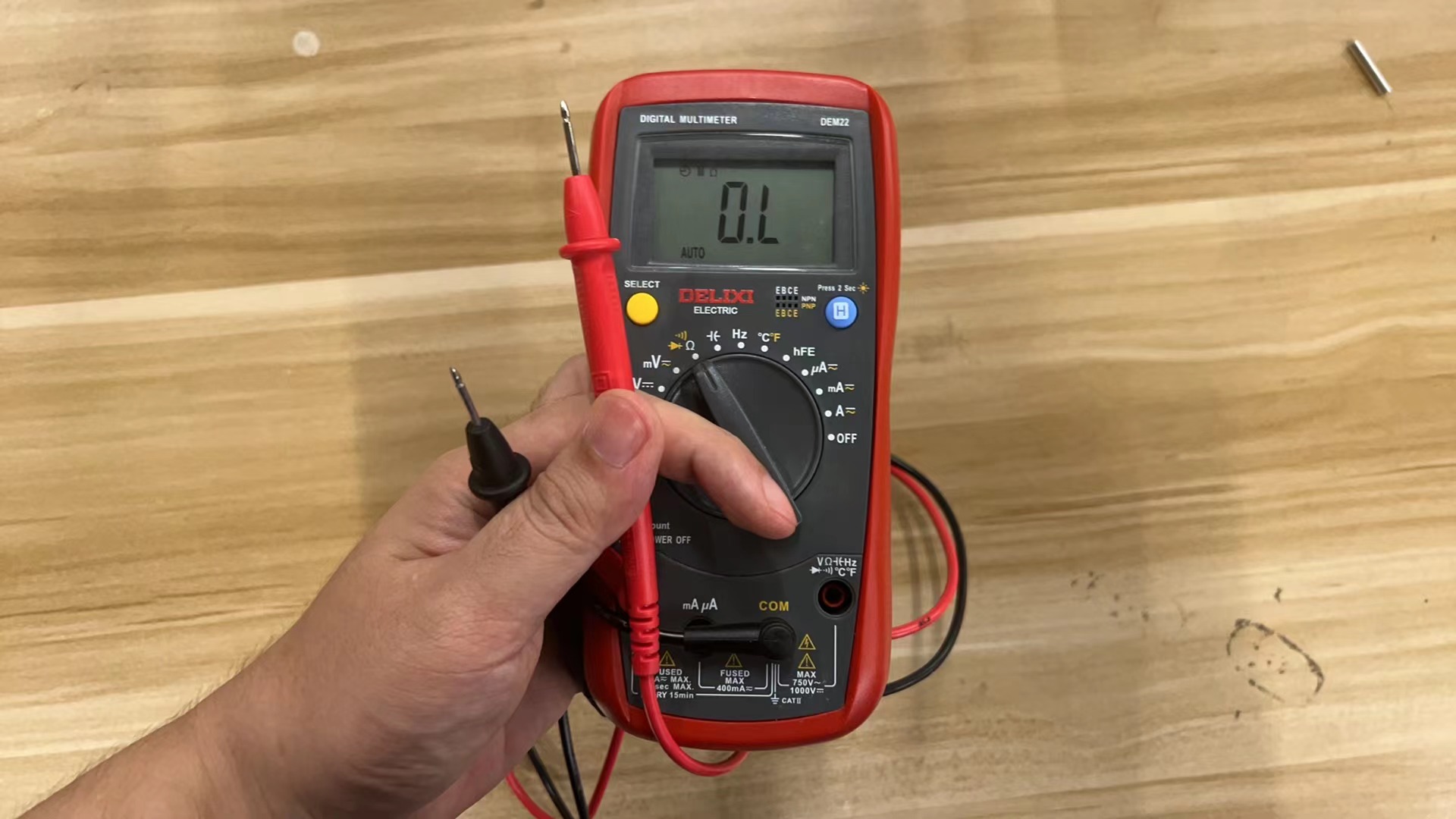
Multimeter
Basic Steps to Use a Multimeter:
Select the Correct Mode: Depending on what you need to measure (voltage, current, resistance), set the dial on the multimeter to the correct function.
Connect the Probes: For most measurements, connect the black probe to the common terminal and the red probe to the appropriate terminal (voltage, ohm, or mA).
Measurement:
Voltage: To measure voltage, place the probes across the component or part of the circuit where you want to measure the voltage.
Current: To measure current, the circuit must be opened, and the multimeter must be placed in series with the circuit so that the current flows through the multimeter.
Resistance: To measure resistance, ensure the circuit power is off and place the probes across the component to measure its resistance.
Continuity: The multimeter will emit a tone if there is continuity (i.e., a complete path) between two points.
Send the board to the Design House
Assignment files
Let's Jump to the Top !!!